Introduction
This guide will introduce you to all the different menus and icons you will see while operating the BOY 22A Injection Molder. This covers only frequently used settings for each screen. For more information, reference the instructions for use document or press the ? key on the machine control system (Procan ALPHA 2).
-
-
Header of the screen page
-
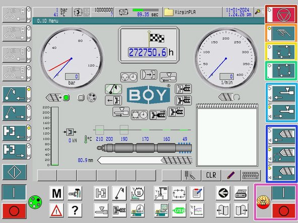
Operating keys on the left-hand screen page
-
Operating keys on the right-hand screen page
-
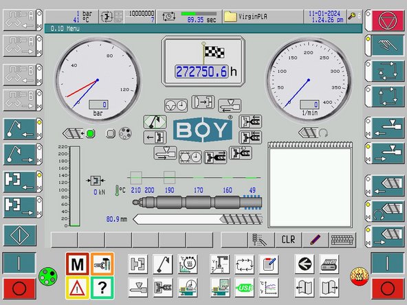
Operating keys below the screen page
-
Footer of the screen page
-
-
-
The header contains important general information. These lines are identical on all screens.
-
The current system pressure and oil temperature are displayed. Touching this icon brings you to the "Machine Equipment Data 1" screen.
-
Here, you can set the oil temperature. This should be at 40°C.
-
The bar shows the sequence of the current cycle. The time shown is the cycle time of the preceding cycle.
-
The currently loaded setup data record is shown. Touching this icon brings you to the "Data Records" screen.
-
Here you can load and write different material settings. Specific details will be discussed in a future guide.
-
This displays the access authorization level, ranging from 0 to 6. Touching this icon brings you to the "Password Entry" screen.
-
Access authorization is needed to change machine settings. Ask injection molder technician for login details.
-
-
-
In the footer, up to eleven keys are shown. Depending on the screen you are on, there are screen-related functions that appear. This will be discussed further along in the guide.
-
Example of screen-related functions/tabs
-
-
-
All operating keys are operated by a light touch on the respective keypad.
-
Each key has 3 features
-
Key symbol: the operation button for a function.
-
Press and hold the key to reach the function limit.
-
Circular yellow light: indicates that the function is at it's position limit.
-
Green bow tie light: indicates that the operation function is active.
-
-
-
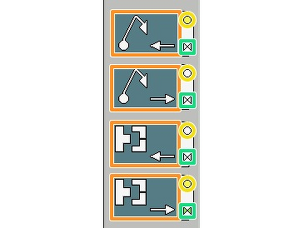
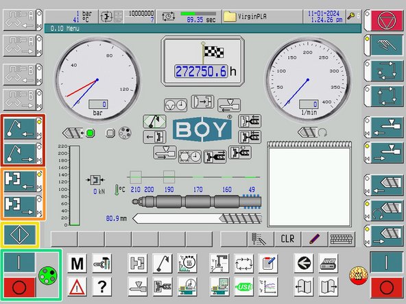
Ejector Movement Buttons: retract ejector (top), advance ejector (bottom).
-
Mold Clamping Buttons: open mold (top), close mold (bottom).
-
Cycle Start Button: cycle starts when pressed.
-
While in semi-automatic or full automatic mode, if all start conditions are met, button will flash green.
-
Drive Motor Buttons: on (top), off (bottom).
-
This heats the oil. "Gear" icon turns green and spins when turned on.
-
-
-
Selector Switch: use this key to stop semi-automatic or automatic cycles.
-
For some operations, such as loading set-up data, you need to be in this operating mode
-
Manual Mode: use this mode to operate parts of the machine such as moving the ejector pins, mold clamp, plasticizing unit, and screw.
-
Semi-Automatic Mode: use this mode to run a single cycle.
-
Fully Automatic Mode: use this mode to run multiple cycles. Press the selector switch to stop.
-
Plasticizing Unit Movement Buttons: move unit forward (top), move unit backward (bottom).
-
Screw Movement Buttons: inject (top), plasticizing (middle), decompression (bottom).
-
Cylinder Heater Buttons: on (top), off (bottom). The "flame" icon turns red and moves when on.
-
-
-
Here, we are only identifying the operating keys. Each key takes you to a different screen page. More in depth information on the screen pages will be discussed later.
-
Menu Screen
-
Machine Settings
-
Error Report Screen
-
Help Page
-
Selecting this takes you to the BOY user manual for the screen you are on. This provides information detailing each setting on the screen.
-
-
-
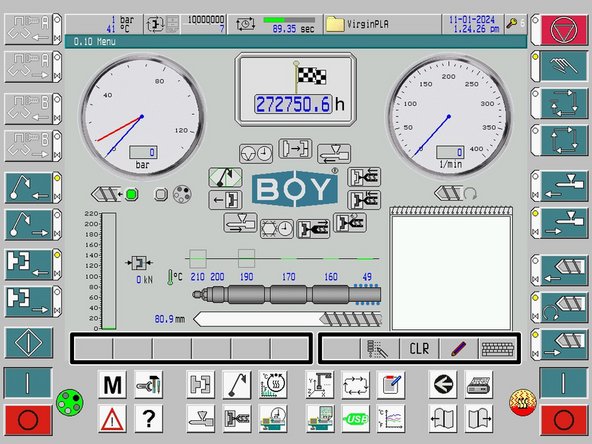
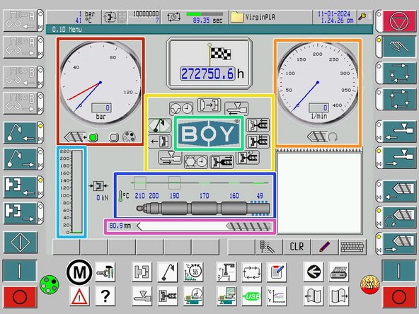
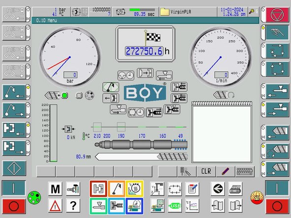
There are no settings to change on the menu page. The page provides an overview of the system, with values that are helpful to monitor during a run.
-
Pressure gauge: injection pressure (screw key), system pressure (gear key)
-
Tachometer: displays screw speed
-
Cycle Direct Selection Keys: pressing a key takes you to the associated screen page. Cycle moves in a clockwise direction.
-
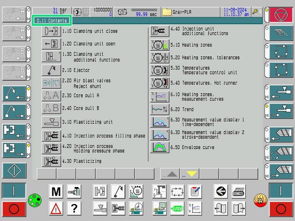
BOY Logo: takes you to the table of contents of all existing pages.
-
Clamping Force: 220kN maximum
-
Cylinder Temperature: displays current temperatures. (green = at working temperature, blue = below temperature, red = above temperature)
-
Screw Position
-
-
-
Here, we are only identifying the operating keys. Each key takes you to a different screen page. More in depth information on the screen pages will be discussed later.
-
Clamping Unit Screens
-
Ejector Screen
-
Heating Cylinder Screen
-
Plasticizing Unit Screen
-
Injection Process Screens
-
Cycle Time Screen
-
-
-
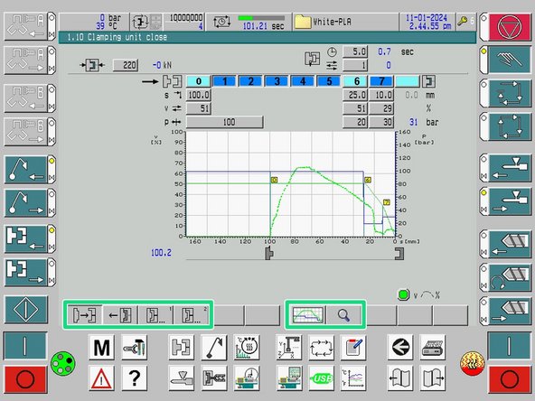
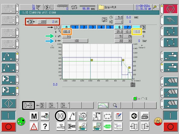
Clamping Unit Close
-
Clamping Force: set the desired clamping force in the rectangle. The value in blue displays the systems current clamping force.
-
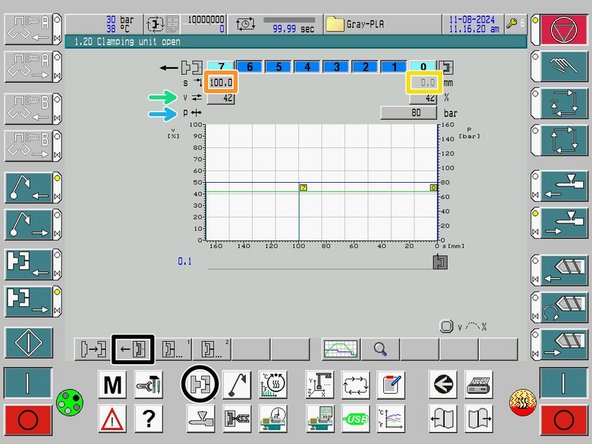
Set-Up Open Value: set the distance you want the mold to open up to.
-
Set-Up Close Value: zeroed while in set-up mode.
-
Clamping Speed: speeds run in a ramp-like manner between the set positions. Each entered position must have a corresponding speed.
-
Travel Pressure Limitation
-
-
-
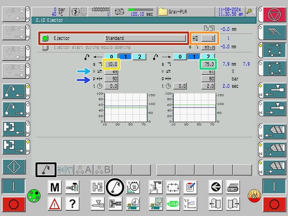
This guide will only describe the frequently used settings for the page. For more information, reference the instructions for use document or press the ? key.
-
The ejector program/setting we use. Do not change.
-
Ejector Strokes: enter the number of ejector strokes (minimum of 1)
-
Set-Up Rear Value: position is entered at which the ejector is retracted in its start position. This value should not need to change for our mold configurations.
-
Set-Up Advance Value: position is entered at which the ejector pin is past the mold. This value may change depending on the mold thickness.
-
Ejector Speed
-
Ejector Pressure Limitation
-
-
-
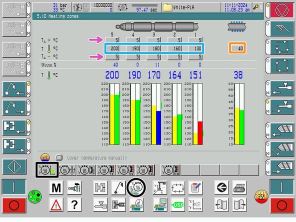
Temperature for feed zone
-
Temperature for heating zones
-
Tolerance values for heating zones. Top is positive and bottom is negative.
-
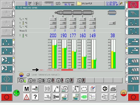
The bar graphs are differentiated by color as follows: After heating zones have reached their set-up values, an idle time of 3 minutes starts to ensure better heat soak of the material.
-
Set-up value
-
Actual value is below set temperature.
-
Actual value is within operating range.
-
Actual value is above set temperature.
-
-
-
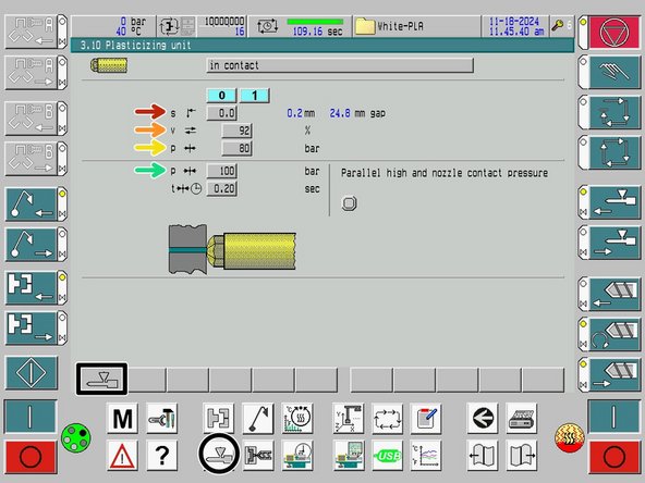
Set-up Nozzle Front Limit: zeroed while in set-up mode.
-
Travel Speed: speed at which the unit moves forwards and backwards.
-
Travel Pressure Limitation
-
Contact Pressure
-
-
-
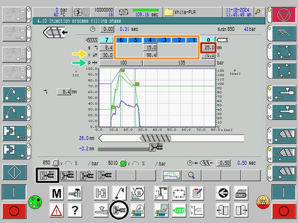
Injection Screw Rear Distance: adjusts shot length/size
-
Injection Profile Input: if no changes in injection speed or pressure limitation, points can be deselected.
-
Screw Speed
-
Pressure Limitation
-
-
-
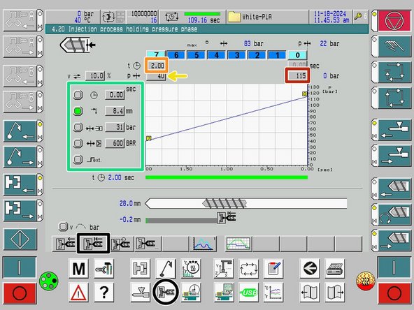
Holding Pressure Start Value: set the starting pressure for the holding phase.
-
Holding Pressure End Time: set the duration of the holding phase.
-
Holding Pressure End Value: set the end pressure for the holding phase.
-
Here, our holding pressure start is stroke dependent. The holding pressure starts at injection position 8.4mm or profile point 7.
-
There are 5 options to switch over to holding pressure. Reference the manual for details about the other options.
-
-
-
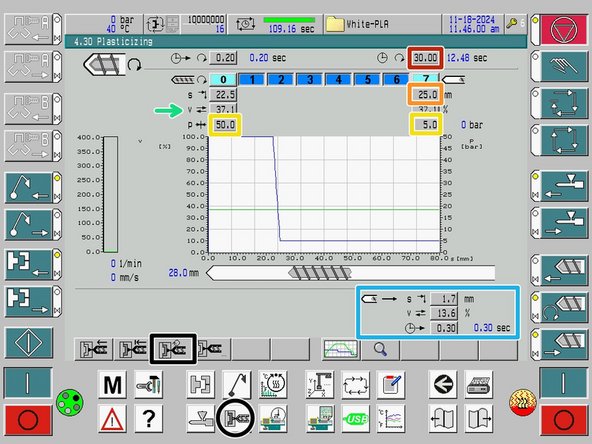
Plasticizing Time Monitor: if the monitoring time expires before plasticizing has been terminated, then fault message appears.
-
Indicates a potential jam in the barrel or insufficient plastic loaded.
-
Entering 0 switches the monitor off. Use this setting when calibrating new material/mold.
-
End Plasticizing Value: corresponds to the shot size input on the filling phase screen.
-
Back Pressure: [ 0 ] start, [ 7 ] end
-
Screw Speed
-
Decompression: stroke, speed, and delay.
-
-
-
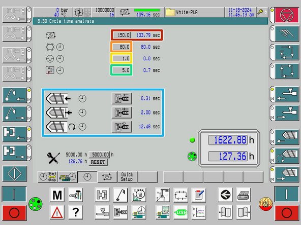
Cycle Time Monitoring: set to be longer than current cycle time. If time set is exceeded, then the machine will be switched off.
-
Cooling Time: starts at the end of the holding pressure phase.
-
Break Time: starts on completion of a cycle (part ejected). After time expires, the next cycle will be started in full automatic mode.
-
Mold Safety Time: if time expires before mold is closed, fault message will appear.
-
Can be caused if previous part was not successfully ejected.
-
Actual times for injection process phases.
-
Blue numbers are the actual time values of the current cycle.
-


