Introduction
Custom Mold Google Drive Folder
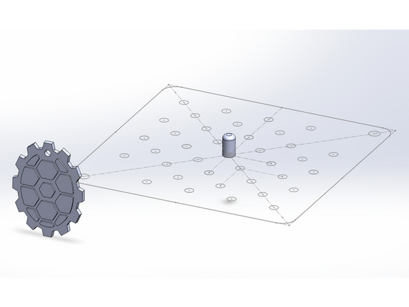
Download Custom Mold Guide.SLDPRT. This file provides the mold dimensions and ejection pin layout compatible with the Terrapin Works Boy 22 A injection molding setup.
Before beginning this guide, the part you intend to injection mold should already be fully designed.
This tutorial demonstrates the process of creating a Terrapin Works keychain mold in SolidWorks using an example part. If you would like to follow along, download Testudo Keychain Undrafted Part.SLDPRT. The correctly drafted version of the part, along with the completed mold, is also available in the folder.
Note: Make sure you are signed in with your umd.edu account when accessing the Google Drive folder. Otherwise, you may encounter permission errors.
-
-
Draft analysis ensures there is an adequate draft angle so your part can be ejected without problems.
-
Draft angles are slight tapers added to vertical walls of the part to prevent it from getting stuck or damaged during ejection.
-
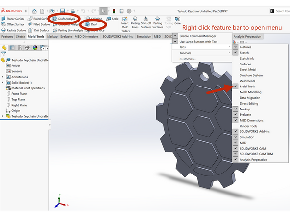
The Draft Analysis and Draft features can be found in the Mold Tools tab.
-
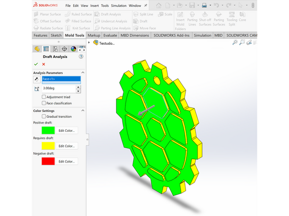
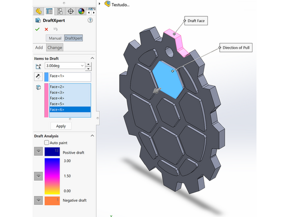
Select the positive face that will serve as the reference (zero) for the draft analysis.
-
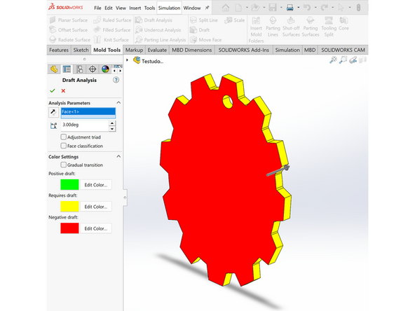
Coplanar or parallel surfaces on the same side of the part are highlighted in green, while surfaces on the opposite side are highlighted in red. Yellow indicates surfaces outside of the specified draft angle tolerance. Here, the tolerance is set from 0 to 3 degrees from the perpendicular to the reference face, so those surfaces require added draft.
-
In this example, the front face is selected. This face will be oriented toward the inside of the mold, so the edges should be drafted to taper toward it.
-
-
-
Select the Draft feature (navigation instruction in Step 1), choosing the positive face from your draft analysis to act as the Neutral Plane.
-
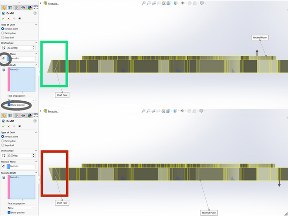
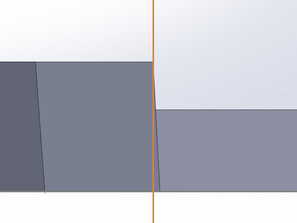
If you select a face on the opposite side of the part or flip the pull direction from the Neutral Plane, the taper will draft in the opposite direction. This is visualized in Image 1 using a 20 degree draft angle applied to a face on the side of the part. The show preview option is enabled to show the change from the original face angle.
-
Select all faces that require a draft angle as determined in Step 1.
-
Apply a draft angle appropriate for your part. Typically, this will be 1-3 degrees, depending on design constraints and manufacturability. For most basic designs though, a 3 degree draft angle can be used.
-
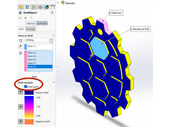
After applying the draft, verify your work by running the draft analysis again. Surfaces with the required draft will now be highlighted in green.
-
Tip: To view your draft analysis simultaneously, you can check the Auto Paint box in the lower section of the DraftExpert (Draft) feature.
-
It is important to note that draft angles can only be applied to uniform surfaces. If you find, for instance, that a portion of a curved surface does not meet draft requirements, you may need to modify the part design, or the part may not be suitable for injection molding.
-
While this example uses a mold with the part entirely on one insert, most custom designs require the part to be split between both mold inserts. In these cases, determine the parting line in advance, split the part accordingly, and analyze and apply draft to each section separately before importing both halves together (Step 3) and realigning them.
-
-
-
Open the Custom Mold Guide.SLDPRT file.
-
From the menu bar, select Insert > Part to insert your drafted part.
-
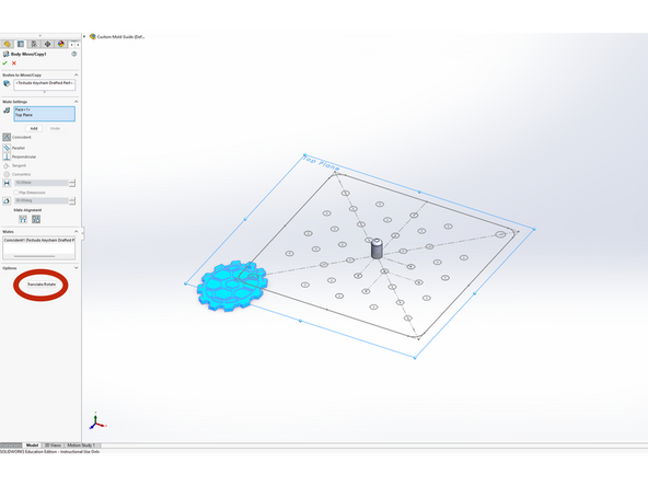
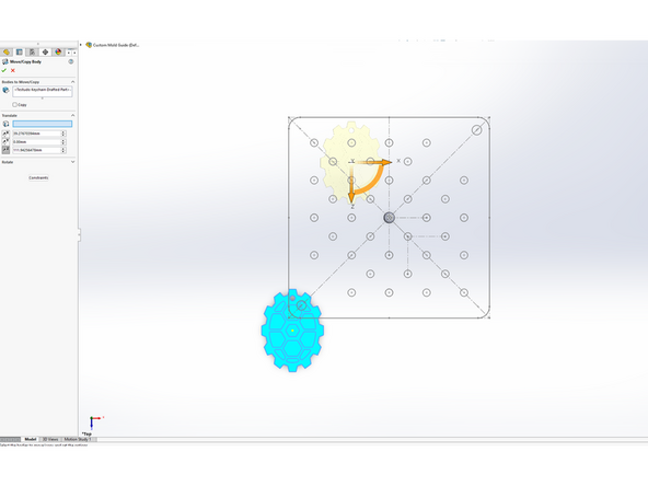
Use Move/Copy feature to align part with guide sketches. Keep in mind that the part will be duplicated in the next step when positioning it.
-
Use constraints to align part with top plane.
-
Use the translate and rotate tools to position the part between the mold insert halves (if necessary) and align it with the ejection pin holes. Distribute the pins as evenly as possible across the part, using as many pins as practical (particularly for larger or more complex parts) without creating visible defects or interfering with part features.
-
Note: The Move/Copy tool does not permanently constrain bodies to other features. Each new instance overrides any previously created mating.
-
-
-
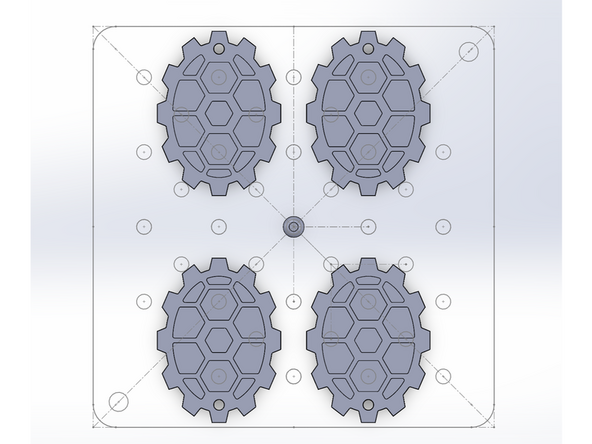
From the menu bar, select Insert > Pattern/Mirror > Mirror to duplicate your part.
-
You can mirror across the default (or your own) planes and use the Move/Copy tool once again to adjust the additional part(s) as needed.
-
-
-
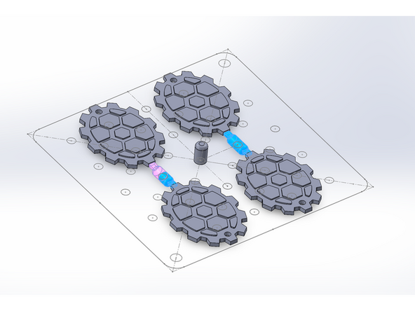
Create one side of the sub runner and filet to smooth.
-
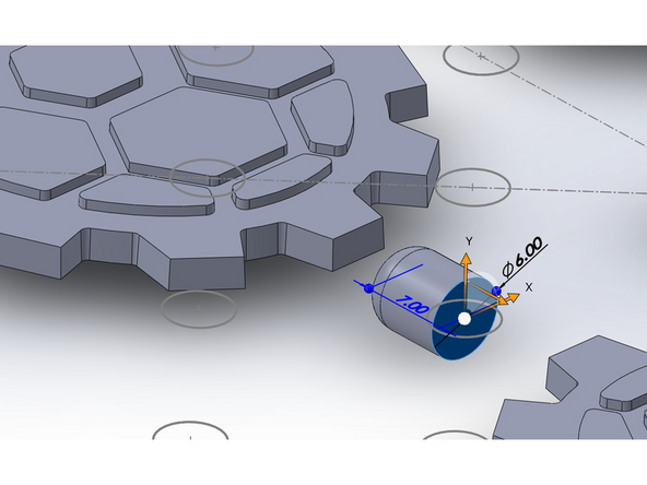
Runners should be straight and at least 6mm in diameter; the main runner and injection hole
-
Create gate
-
This should be flush with the slice plane or guide sketch plane.
-
The sketch plane should be perpendicular to the top face of your part, since the walls are drafted.
-
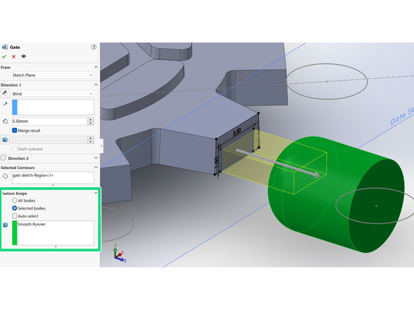
Extrude gate to sub runner
-
Sub runner and gate bodies should be merged together but not to your part (helps with duplicating via mirroring).
-
Feature Scope > Selected Bodies
-
-
-
Duplicate/Mirror sub runner gate body if you have multiple parts.
-
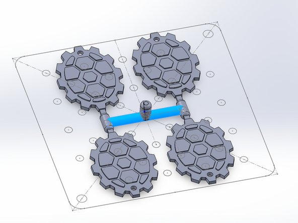
Merge sub runners together
-
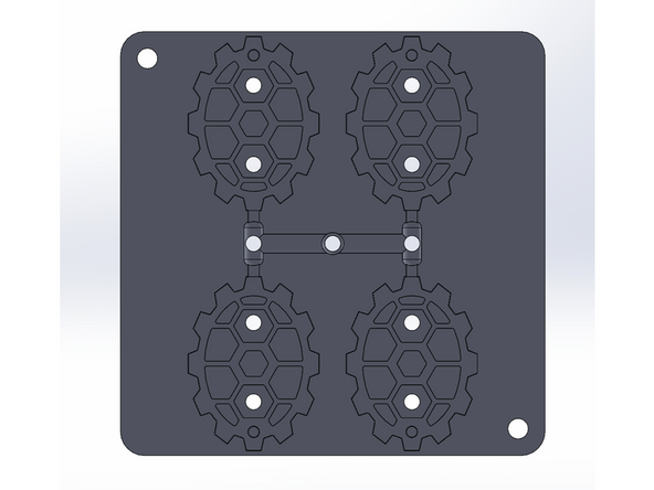
Add main runner connecting sub runners and cold slug.
-
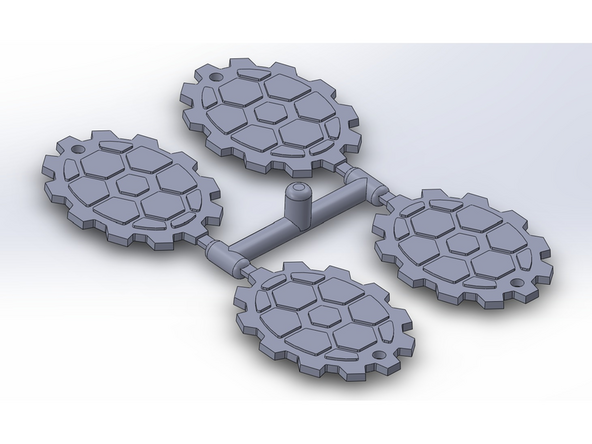
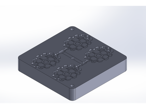
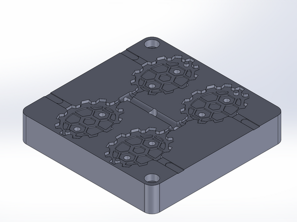
Combine all bodies. This should be your desired mold cavity!
-
-
-
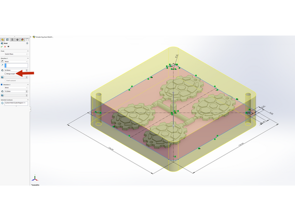
Extrude 'Custom Mold Guide Sketch'
-
24.9mm / 0.98 in up (Side B)
-
15.2mm / 0.6 in down (Side A)
-
Uncheck merge results. You should have 2 bodies after this operation!
-
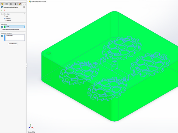
Use the 'Combine' feature and select subtract.
-
Main Body: Mold Block
-
Bodies to Combine: Mold Cavity
-
-
-
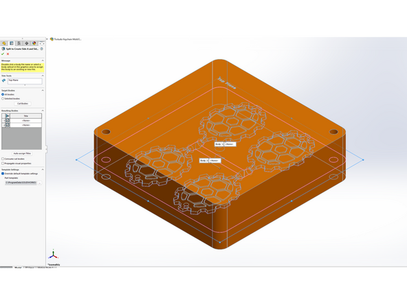
Use 'Split' feature to create Side A and Side B.
-
Trim Tool: plane of 'Custom Mold Guide' sketch
-
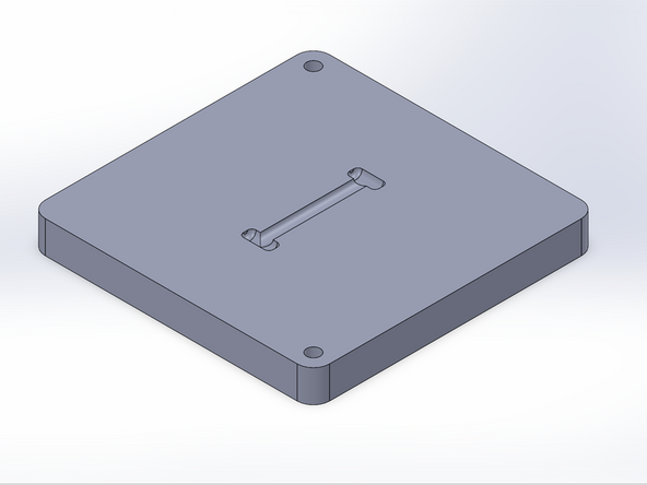
Check for both resulting bodies.
-
Side A
-
Side B
-
-
-
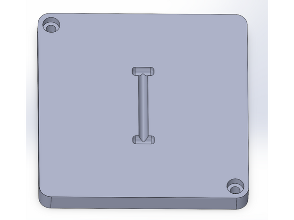
Ejection pins push the mold part out of the mold cavity after injection. We need to create holes in our mold to allow for the ejection pins to slide through.
-
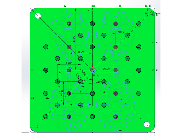
Use 'Custom Pin Guide' sketch to select contours to extrude cut into Side B
-
Select all applicable ejection pin holes to your design.
-
Remember you need ejection pins for the runners and cold slug as well.
-
-
-
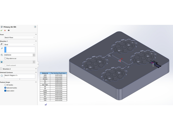
Proper venting ensures that air and mold gas release are effectively conducted during the injection process
-
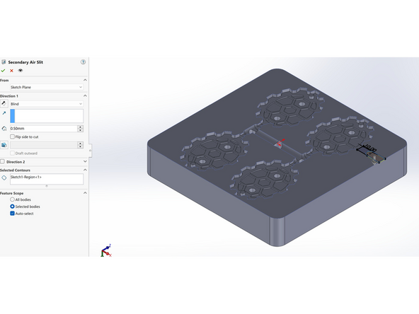
Create sketch for air slits on Side B of the mold.
-
Extrude cut the Secondary Slit by 0.5mm
-
Extrude cut the Primary Slit by value value determined by material
-
Duplicate air slits so each part is vented.
-
[pull references from textbox, explain issues that can occur and different design types]
-
-
-
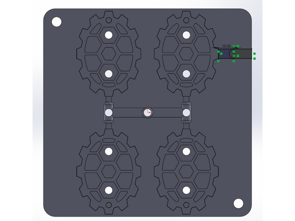
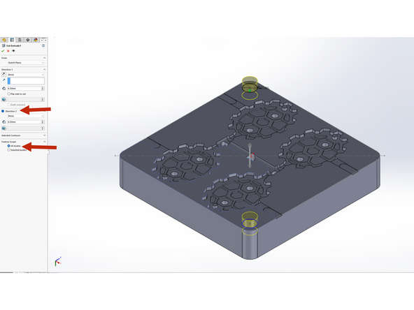
Extrude cut 11mm counterbore pattern from 'Custom Mold Guide' by 6.2mm on both sides, and set the feature scope to all parts.
-