Introduction
Custom Mold Google Drive Folder
Download 'Custom Mold Guide.SLDPRT'. This provides the dimensions of the mold and ejection pin layout that is compatible with our set up.
Before starting this guide, the part you wish to be injection molded should be fully designed.
This tutorial will go through the creation of a TW Keychain mold as an example. The results can also be found in the folder linked above.
-
-
Draft analysis ensures there is an adequate draft angle so your part can be ejected without problems.
-
'Draft Analysis' feature can be found in the 'Mold Tools' tab.
-
Select the positive face that will serve as a zero for the draft analysis.
-
In this example, the frontside is chosen as we want to draft into this face.
-
Direction matters in some cases!
-
The yellow faces indicate the faces that require added draft.
-
-
-
Use 'Draft' feature located in the 'Mold Tools' tab.
-
Select the positive face from your draft analysis as the Neutral Plane.
-
Select all faces that require a draft angle determined in step 1.
-
Apply a draft angle that works for your part. Usually 1-3 degrees.
-
When necessary faces are drafted, the draft analysis will show them as green.
-
-
-
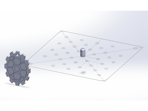
Open 'Custom Mold Guide.SLDPRT' file
-
Insert your drafted part using the 'Insert Part' feature.
-
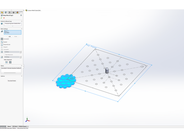
Use ‘Move/Copy Bodies’ feature to align part with guide sketches.
-
Use constraints to align with top plane.
-
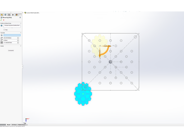
Use rotate/translate to align with pins.
-
-
-
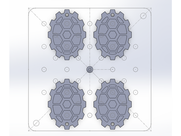
Use 'Mirror' feature to duplicate part if needed.
-
-
-
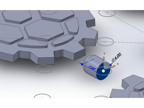
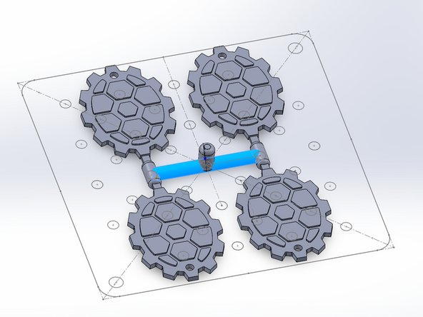
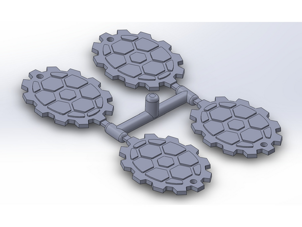
Create sub runner and filet to smooth
-
Runners should be 6mm or larger
-
Create gate
-
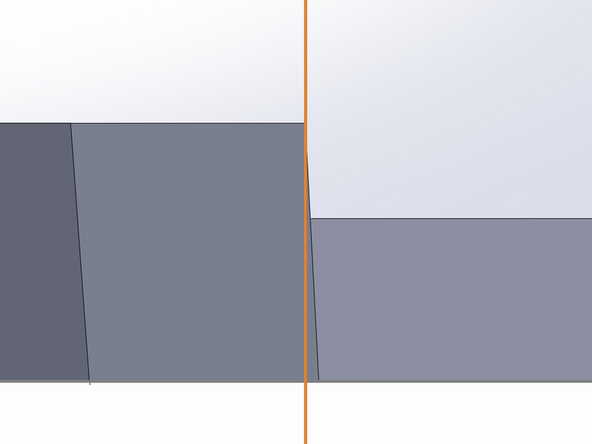
This should be flush with the slice plane or guide sketch plane.
-
The sketch plane should be perpendicular to the top face of your part, since the walls are drafted.
-
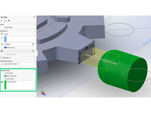
Extrude gate to sub runner
-
Sub runner and gate bodies should be merged together but not to your part (helps with duplicating via mirroring).
-
Feature Scope > Selected Bodies
-
-
-
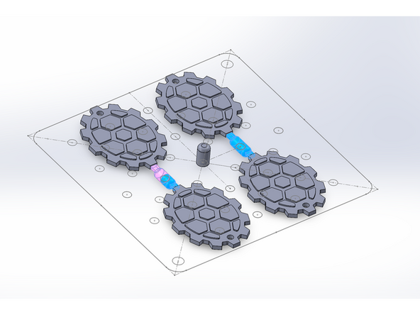
Duplicate/Mirror sub runner gate body if you have multiple parts.
-
Merge sub runners together
-
Add main runner connecting sub runners and cold slug.
-
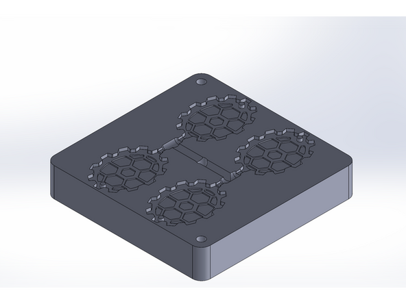
Combine all bodies. This should be your desired mold cavity!
-
-
-
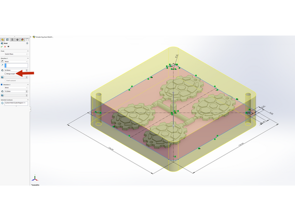
Extrude 'Custom Mold Guide Sketch'
-
24.9mm / 0.98 in up (Side B)
-
15.2mm / 0.6 in down (Side A)
-
Uncheck merge results. You should have 2 bodies after this operation!
-
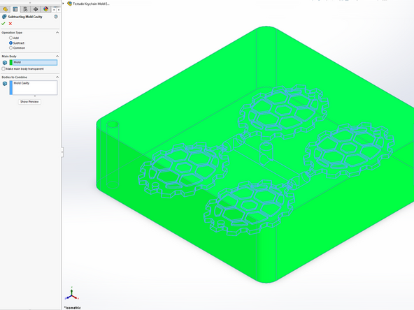
Use the 'Combine' feature and select subtract.
-
Main Body: Mold Block
-
Bodies to Combine: Mold Cavity
-
-
-
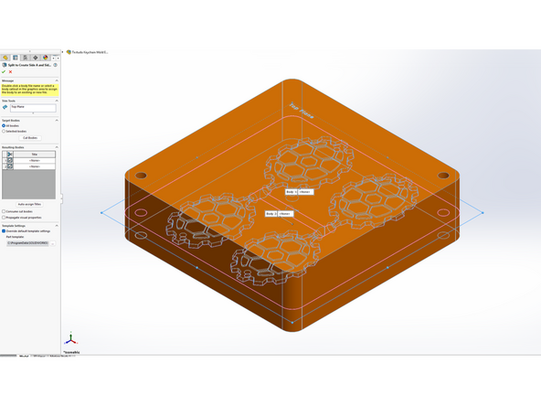
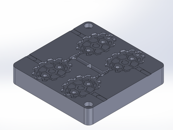
Use 'Split' feature to create Side A and Side B.
-
Trim Tool: plane of 'Custom Mold Guide' sketch
-
Check for both resulting bodies.
-
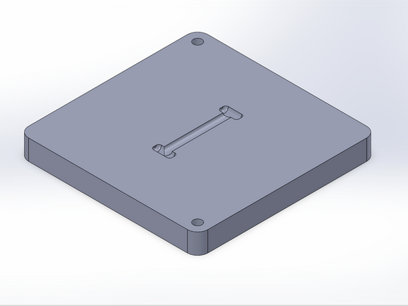
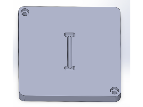
Side A
-
Side B
-
-
-
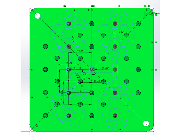
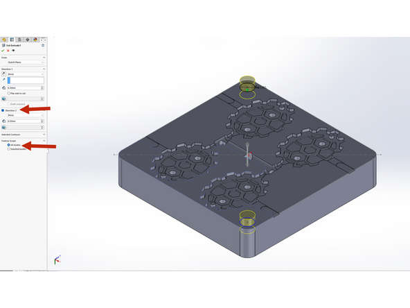
Ejection pins push the mold part out of the mold cavity after injection. We need to create holes in our mold to allow for the ejection pins to slide through.
-
Use 'Custom Pin Guide' sketch to select contours to extrude cut into Side B
-
Select all applicable ejection pin holes to your design.
-
Remember you need ejection pins for the runners and cold slug as well.
-
-
-
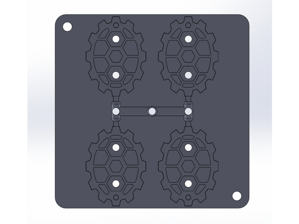
Proper venting ensures that air and mold gas release are effectively conducted during the injection process
-
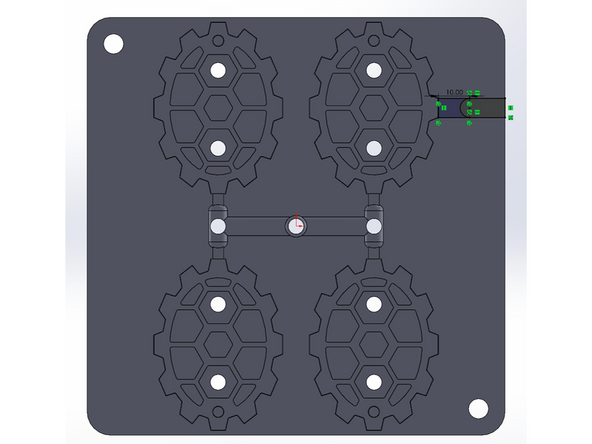
Create sketch for air slits on Side B of the mold.
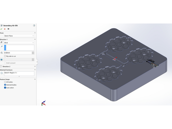
-
Extrude cut the Secondary Slit by 0.5mm
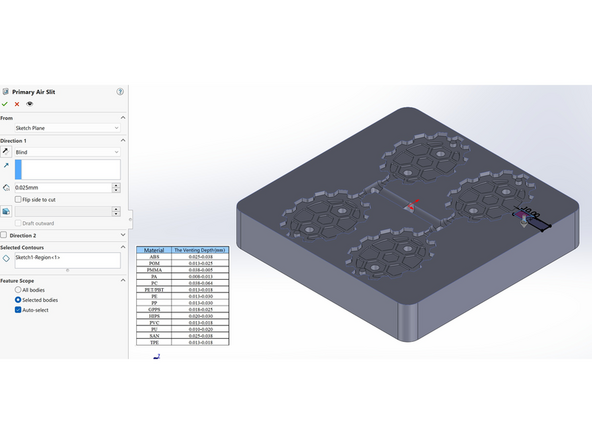
-
Extrude cut the Primary Slit by value value determined by material
-
Duplicate air slits so each part is vented.
-
-
-
Extrude cut 11mm counterbore pattern from 'Custom Mold Guide' by 6.2mm on both sides, and set the feature scope to all parts.
-