
-
-
Open your .dxf or .dwg file in Illustrator. Make sure you select the correct scale your file was drawn, inches, mm, and set the scale as 1=1
-
Select/click on any lines that are to be cut lines, and change the stroke to .001 . There should be no infill and the opacity should be 100%
-
Anything that is not .001 will be rastered/engraved
-
In order to send your print to the printer. Select File then select Print
-
-
-
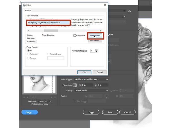
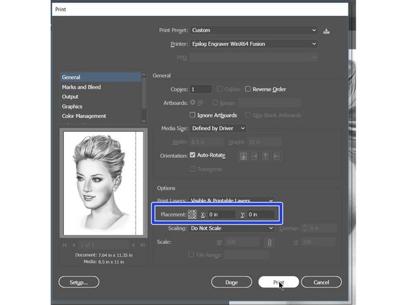
When you are on the print screen be sure to select the Epilog as your printer
-
Now select the Setup button in the lower left corner. This opens up an additional menu
-
-
-
Double check that the Epilog printer is selected and click on the preferences button
-
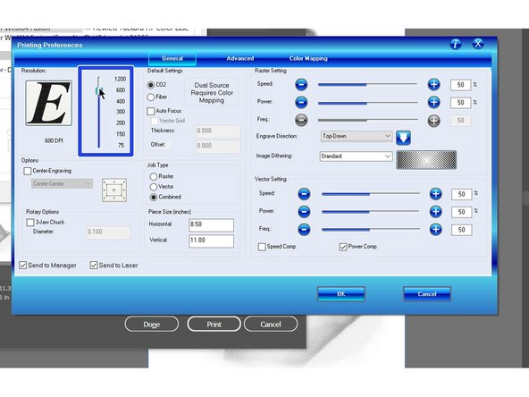
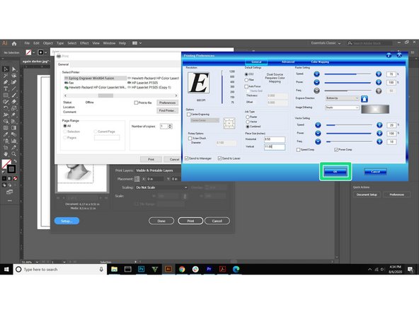
Epilog controls page will now be open. Select the Dpi for your project
-
The higher the Dpi the better the resolution. This will also affect the print time. 600 Dpi is usually a good compromise
-
Select the job type. Raster (engraving), or Vector (cutting), or combined
-
-
-
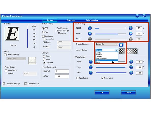
If you are rastering your job, you will need to adjust the speed and power setting according to the chart. You should also adjust the image dithering to Jarvis or Stucki for best results.
-
When cutting material you will need to adjust the speed, power and frequency according to the materials chart.
-
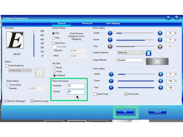
Be sure to change the size to 32" horizontal and 20" vertical to match the cutting bed size of the Epilog.
-
-
-
This chart should be used as a reference for speed and power for each material approved for use on the Epilog. Only materials on this chart can be used on the Epilog.
-
For reference this chart can be found on page 197,198 in the Epilog manual. https://www.epiloglaser.com/assets/downl...
-
There is a hard plastic copy of the recommended materials list with settings on the Epilog.
-
Sometimes you will have to fiddle with the exact speed and power settings to get ideal results
-
Click the OK button when all your setting are finalized
-
-
-
Check that the X=0 and Y=0 placement. You can also click the top left corner of the little hashtag pattern #.
-
This will allow us to line up the top left corner of the file with the corner of the material
-


2 Comments
SHow the users how to select epilog in the printer settings
Show users how to setup the power and rastering settings in the prompt
Nathanael Carriere - Resolved on Release Reply
See if you can find some videos for this like the one you showed me earlier to do this instead of having to totally break this into something that is step by step. I am sure someone has created a guide like this for a maker space before. .dxf creation from each of the major software’s as a video is important to have as well. Solidworks, Fusion, Inventor, and NX. Just fins some videos no need for you to know it yourself. Just need to know really here how to open it up and maybe the standard setting to use. We could even link to the specific page here in the manual where people can find setttings if they cant find the aryclic sheet we have in the lab.
Nathanael Carriere - Resolved on Release Reply