
Introduction
This guide reviews the principles and tools behind assembling components into one design in Fusion 360. Note that the process for making assemblies in Fusion 360 differ markedly from that of comparable CAD software.
-
-
Make sure all the solid bodies to assembly are sorted into components
-
Add all relevant components to the same design workspace.
-
You can begin be creating all components in the same workspace
-
Drag and drop previous designs from the data panel to the current design workspace to add them
-
-
-
Fusion 360 assembly relies on features, termed joints, that constrain two components relative to one another. To begin a joint, select the joint button in the Assembly section of the toolbar
-
The first joint in this assembly will constrain the arm between the two walls of the bracket
-
Component 1 moves and component 2 keeps its position. Thus, select the inner cylinder of the arm for the constraining face from component 1.
-
For the component 1 selection, keep the mode as Simple
-
Set the mode as Between Two Faces for component 2
-
Select the two inner faces from the bracket as the two faces used to constrain the joint
-
Select the joint origin as the projection of the cylinder's axis onto the midplane between the two planes previously selected
-
Set the offset in the z direction to insure the arm does not intersect with the bracket
-
-
-
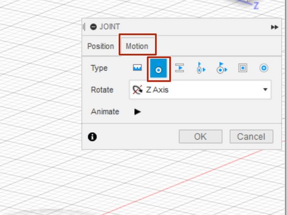
Before hitting Okay on the arm-bracket joint, navigate to the Motion tab. This controls the type of motion allowed by the joint. Select revolve.
-
Open a new joint to affix the pin into the bracket and hold the arm in place.
-
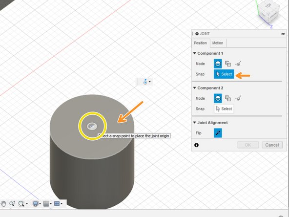
For component 1, select the top face of the pin for a simple snap joint
-
Place the joint origin in the center of the face
-
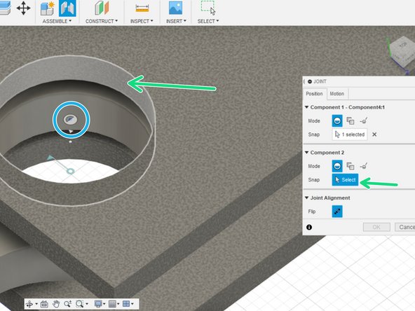
For component 2, select an internal face for a simple snap joint
-
Set the joint origin as the center point of the outside face
-
Make the joint rigid in the motion tab
-
-
-
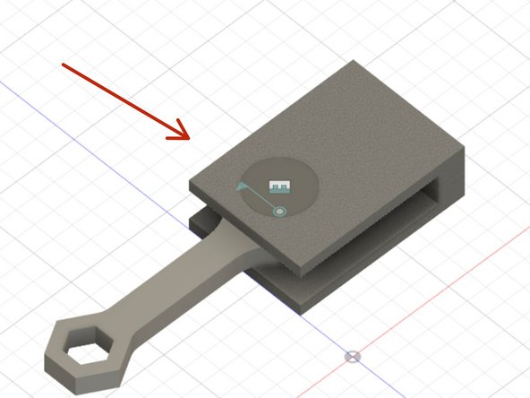
The joints made in the previous steps produced the assembly indicated with the red arrow.
-
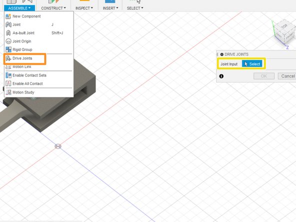
Drive joints constrain the motion allowed by a joint. Otherwise the arm could rotate straight through the solid bracket.
-
The Assembly drop down menu houses the button to open the drive joint window
-
Select the joint to drive
-
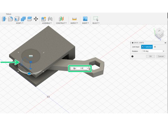
The drive joint tool will present the most appropriate constraint for the type of joint. For a joint with revolution motion, the drive joint tool enables constraining the angle of revolution.
-
Set the angle of revolution allowed
-


Cancel: I did not complete this guide.
One other person completed this guide.