
-
-
The first part of this training series will be to CAM the "UMD M." No CAD will be done with this part, just CAM.
-
If you haven't already, go to IFL - Team in Fusion 360 and create your own Training User Folder under "Datron" --> "!Training" --> "Training User Folders"
-
Name the folder after yourself. This is where you will be doing all your training part CAM programming
-
-
-
Navigate to the M Shape Cutout part. This can be accessed by going to "Datron Projects" > "!Training" > "!Training Parts" > "M Shape Cutout."
-
Right click on the part, and click Copy. Then, navigate to your Training User Folder and click "Copy". This will copy the M Shape Cutout part to your training user folder
-
-
-
Open the M Shape Cutout in your Training user Folder
-
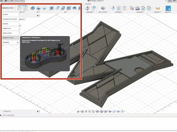
Navigate and click on the "Manufacture" tab
-
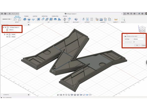
Change the document units to "mm" if not already. This is because the Datron CNC runs in mm and it makes things easier.
-
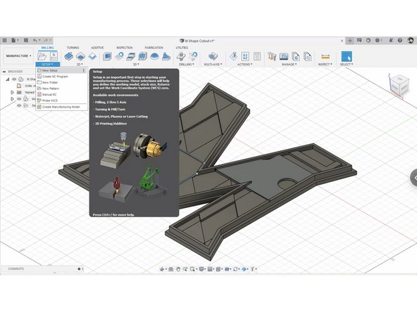
Navigate to and click on "New Setup"
-
-
-
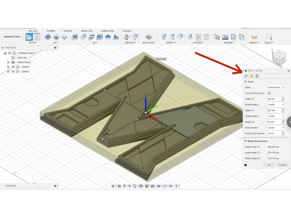
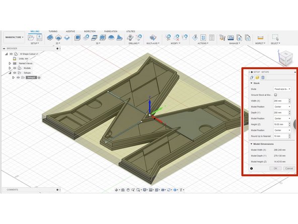
Click on the "Stock" tab in the window pop-up. This tab allows you to specify the size of the stock you are using.
-
For us, we will know the size of our stock. Thus, we will select "Fixed Size Box" next to "Mode"
-
We are using 1/4" thick Aluminum for our stock. This is equivalent to 6.35mm. This is what we will set as our Height (Z)
-
If known, input your Width (X) and Depth (Y) of the piece of stock you are using. If not, leaving the distances as default is fine, as long as the stock you are using is rectangular in shape.
-
Verify that the Work Coordinate System (WCS) is centered on top of the stock. We can always specify our own unique WCS, but it will be simplest for us to probe off the top of the stock, with the WCS centered.
-
Click OK at the bottom of the window when done.
-
-
-
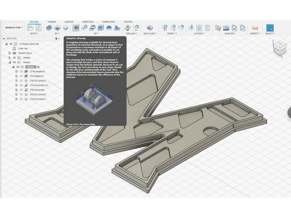
For the first operation, we want to use to face off the extra stock above the part. The most efficient way to face off material in the Datron is to use "Adaptive Clearing" with the facing tool
-
This menu has the settings that will control the facing operation. We will not need to change the Geometry, Heights, or Linking settings for facing
-
In the tool tab click select tool to open the Datron tool library. Inside the tool library select the #10 - 14mm Diameter Face Mill. When tools are imported, they will change the feeds and speeds in the tool tab depending on what tool it is.
-
Set Coolant to Mist since we are cutting aluminum.
-
Each tool in Datron Aluminum is already preset for Aluminum speeds and feeds, so therefore we won't need to adjust anything with speeds and feeds
-
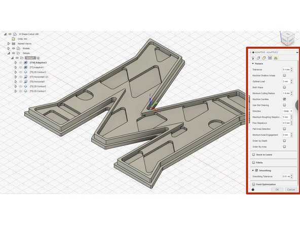
In the "Passes" tab, set Optimal Load as 3mm, Maximum Roughing Stepdown to 5mm, and turn on Smoothing
-
The way you find out about optimal load and step downs in by referencing the Excel sheets pinned in the equip-datron slack channel. Make sure to be conservative when inputting your values compared to the spreadsheet!
-
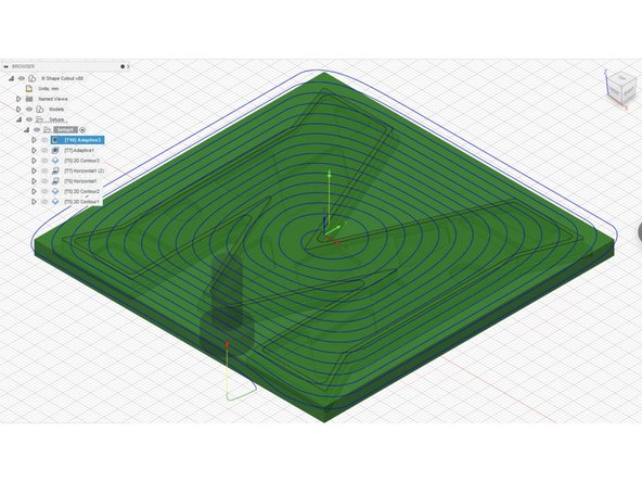
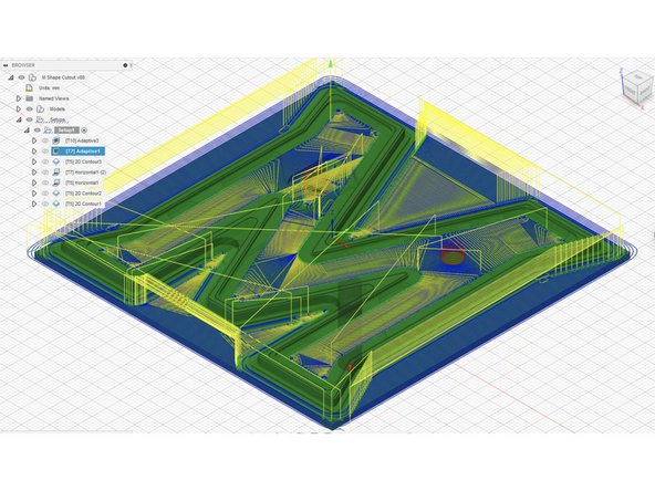
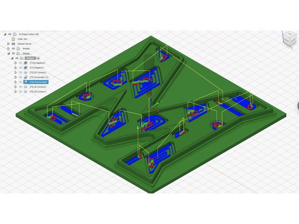
Once settings window is closed Fusion will show the tool path of the face mill over the part. During the CAM process if you ever want to check your work, right click on your setup and select simulate to view the progress of the part.
-
-
-
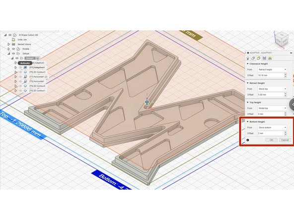
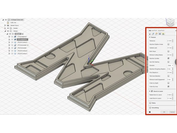
Next operation is another Adaptive Clearing. We want to remove as much material as quickly as possible while leaving a small amount for the finishing operations.
-
Start an adaptive clearing and select the #7 - 6mm flat end mill. Once again, feeds and speeds are already set for the tool.
-
In the Heights tab, in the Bottom Height section, ensure that it is From Stock Bottom and Offset is 2mm.
-
In the Passes tab, set Optimal Load to 0.5mm and Maximum Roughing Stepdown to 8mm
-
-
-
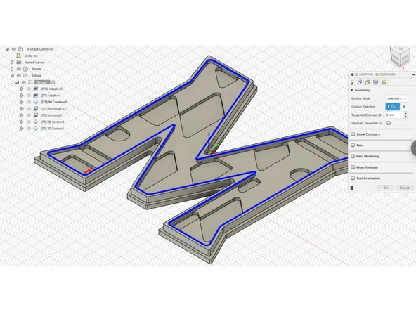
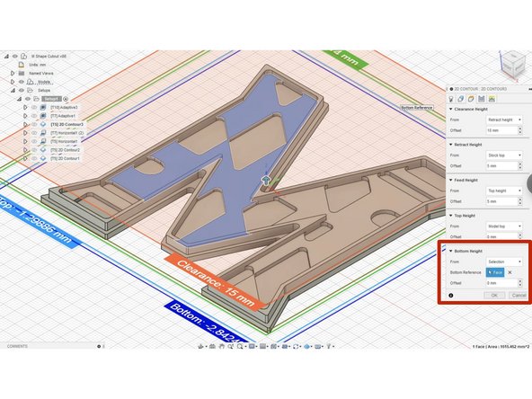
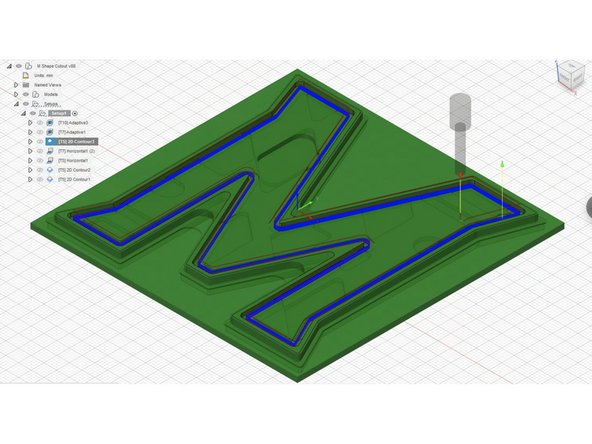
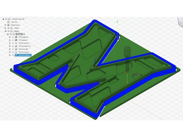
The next operation is 2D Contour. We want to clean up the inside contour of the M to machine it to final dimension and make the cut smooth.
-
For tool, select the #5 - 3mm Diameter Flat End Mill
-
In the Geometry tab, select the top-inside contour of the M as shown in the image
-
In the Heights tab, under Bottom Height, click From Selection. Then on Bottom Reference, click the following face as shown with a 0mm offset. This will tell the 2D contour to mill until the tool hits the top of that face.
-
In the Passes tab:
-
Enable Multiple Depths and set Maximum Roughing Stepdown to 0.2mm
-
Turn on Smoothing
-
In the Linking tab, turn on Ramp. Set Ramp Angle to 2 deg, Maximum Ramp Stepdown to 2mm, and Ramp Clearance Height to 2.5mm
-
-
-
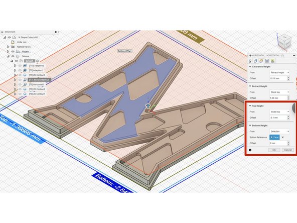
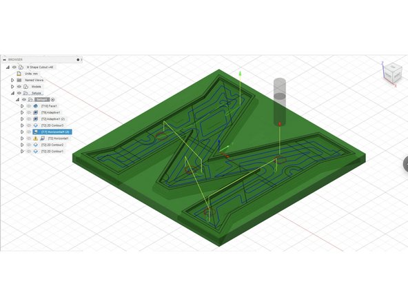
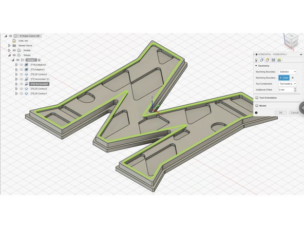
The Horizontal operation will cut all flat surfaces of the part to final dimension.
-
Select Horizontal from 3D operations and select the #7 - 6mm flat end mill tool
-
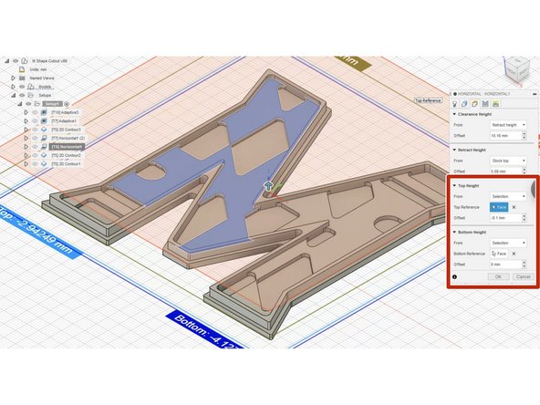
In the Heights tab:
-
In the Top Height section, select From Model Top and set Offset to -0.1mm.
-
This is to tell the toolpath to exclude cutting the horizontal surface of the top lip of the M, which was already cut in the first Adaptive Operation
-
In the Bottom Height section, select From Face and set Offset to 0mm. Select the following face as shown in the image.
-
In the Passes tab, turn Smoothing on
-
-
-
Create another Horizontal operation and select the #5 - 3mm flat end mill tool
-
In the Geometry tab select machining boundary to be the top inside contour as shown. Then in Tool Containment select Tool inside boundary
-
In Heights tab:
-
In Top Height section, select the shown face as Top Reference and set Offset to -0.1mm
-
In Bottom Height section, select one of the recessed faces inside the M as Bottom Reference and set Offset to 0mm
-
In Passes tab, enable Multiple Depths and set Maximum Stepdown as 0.2mm and set Number of Stepdowns to 7. Turn Smoothing on.
-
-
-
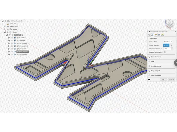
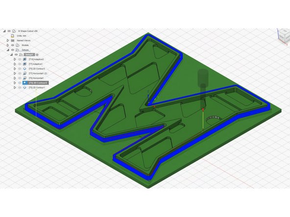
Create a 2D Contour operation to clean up the outer lip. Select the contour as shown in the image.
-
In the Passes tab, enable Multiple Depths and set Maximum Roughing Stepdown to 0.2mm
-
In the Linking tab, enable Ramp and set Maximum Ramp Stepdown to 2mm. Keep other values the same as default.
-
-
-
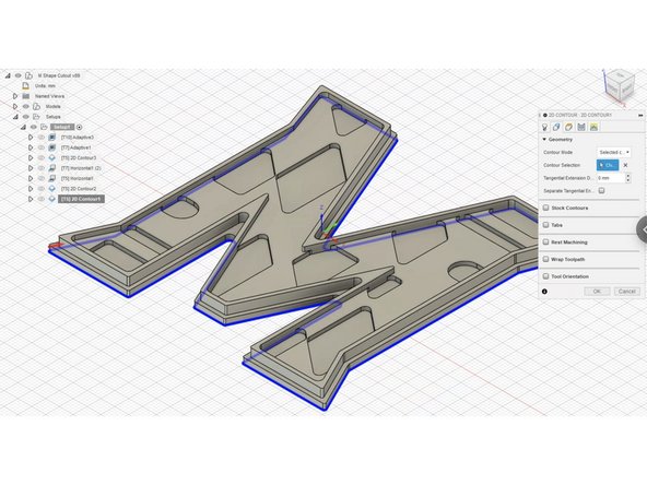
For the final operation we will be using a 2D contour to remove the part from the stock.
-
Select 2D contour and pick the bottom edge of the part shown in the picture.
-
In the Heights tab, change the Bottom Height to -0.1mm from the stock bottom. This will ensure that the part is fully removed from the stock.
-
In the Passes tab, enable Multiple Depths and set Maximum Roughing Stepdown to 0.2mm
-
In the Linking tab, enable Ramp and set Maximum Ramp Stepdown to 2mm
-
-
-
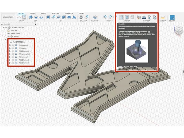
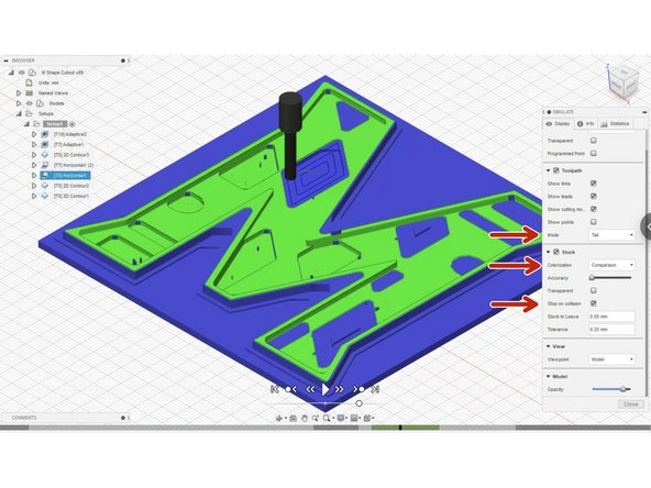
Always simulate before exporting your g-code! This is allows you to check for any errors you have in your toolpath.
-
Click on your setup and then click on Simulate in the top window.
-
Colorization is personal preference, but Comparison is recommended. Also, Tail under Toolpath is recommended
-
Turn on Stop on Collision. This will stop the animation when a collision is potentially detected.
-
Before proceeding to the next step, review your simulation with a staff member who is already trained on the Datron
-
-
-
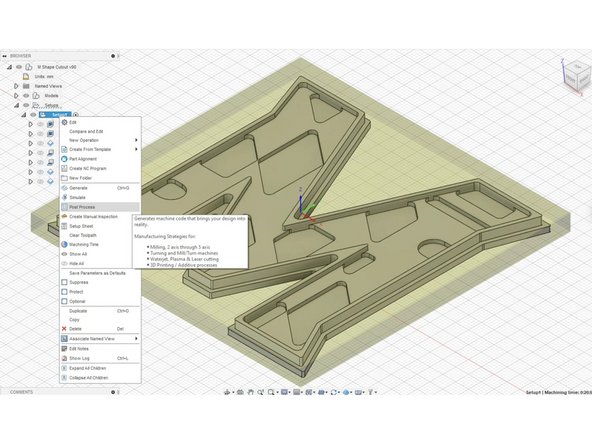
Once your toolpath is ready and has been reviewed by a staff member, right click your setup and click on Post Process
-
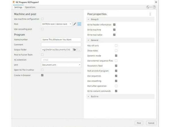
This will take you to the next window where you can name your file whatever you want.
-
For some CNCs, you are limited in how you can name a file. For example, on the Okuma CNC you can only name it a combination of capital letters or numbers (ABC1). But there is no restriction for the Datron.
-
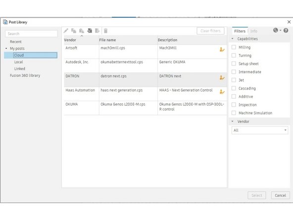
Next, make sure you select the correct post processor. Select the DATRON post processor from the IFL Team Cloud.
-
Finally, you can specify what folder you want your g-code to be outputted to. The file will output as a .simpl file, which is meant to be ready by the Datron.
-
Once you're ready, click Post in the bottom right corner and Save.
-


Team
