
-
-
For starting you will need to get a scan result of the 3D system test scan part
-
You can obtain the scan result by download it from (https://drive.google.com/open?id=1I2NOni...) or perform scan of the part by yourself
-
If you want to generate the model yourself. It is recommended to use Romer Arms to scan the part
-
When you have the scan result ready and open in Geomagic Design X software, go to the next step
-
-
-
Select Auto Segment from the top window under Home
-
The Auto Segment is used to segmented the scan file into multiple segment that can be selected as reference
-
The auto segment result is shown as region group in the top left window (See figure)
-
The auto segment can be hidden by right click on it and select hide
-
-
-
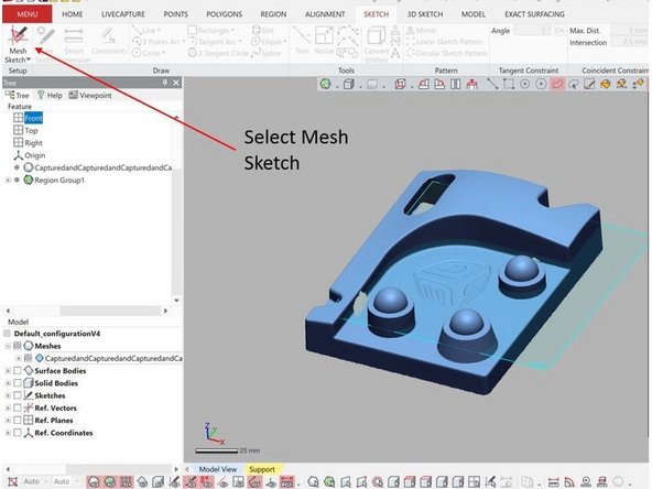
Mesh Sketch is used to create a cross section sketch of the scanned object
-
The Mesh Sketch can be found on the top window under Sketch
-
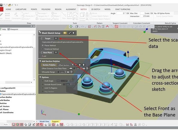
Under Target, select the scan data
-
Under Base Plane, select the front plane
-
Drag the blue arrow up and down to adjust the cross-section sketch (See figure)
-
Try to adjust the arrow to get the cross section view that shown the outer layer of the object
-
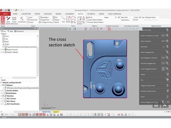
When finished, select the check mark. A cross section sketch will be generated (See figure)
-
-
-
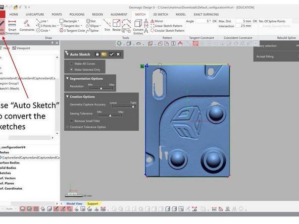
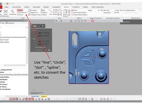
The cross section sketched need to be converted into regular sketches. There are a few option to do this:
-
Use the Auto Sketch to directly convert the sketches
-
Use the cross-section sketches as reference and generate sketches on top of that
-
For this you can use line, circle, slot, spline, etc. feature to convert the sketches
-
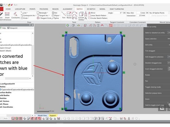
The converted sketches are shown with blue color
-
Make sure that you generate an enclose sketch as the sketch will be use for extrusion in the next step
-
-
-
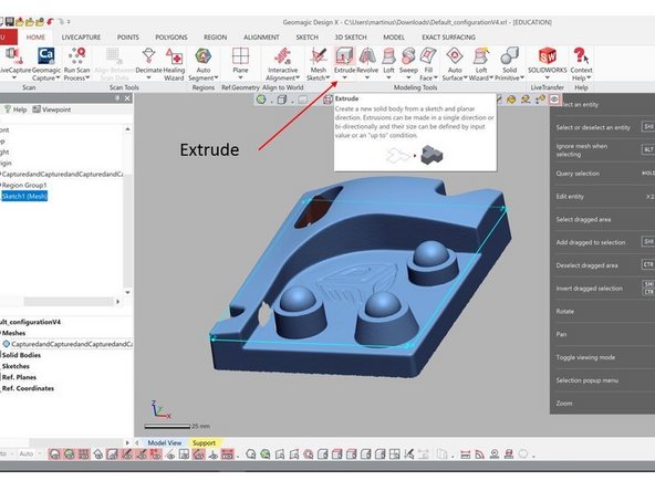
Now you want to extrude the sketch to form a solid body
-
The extrude feature can be found on the top window under Home
-
Select the sketch generated from the previous step as the extrusion profile
-
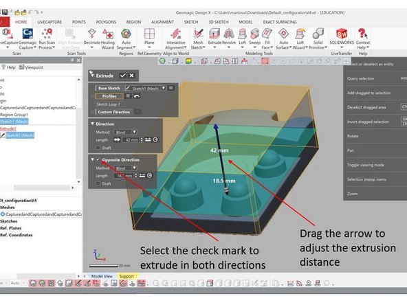
Select the check mark under Opposite Direction to extrude in both directions
-
Drag the arrow to adjust the extrusion distance
-
For the bottom, extrude it all the way till the end of the scan. For the top, extrude it higher than the scan structure
-
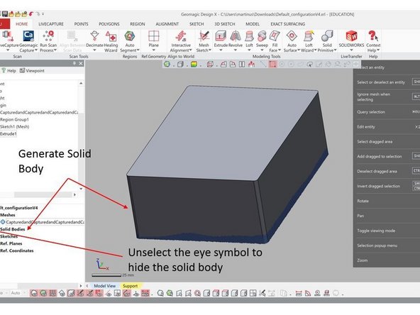
When finish, select the check mark and a solid body will be generated (See figure)
-
Unselect the eye symbol to hide the solid body
-
-
-
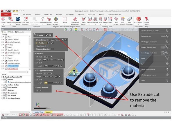
Extrude cut is used to remove a section of a body
-
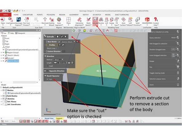
Before performing an extrude cut, create a sketch of the internal section of the geometry as shown in the figure using Mesh Sketch as explain in the previous step
-
The Extrude cut option is the same as the previous Extrude option. Make sure that the Cut option under Result Operator is checked
-
Use the sketch as reference for the cut
-
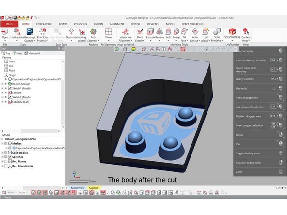
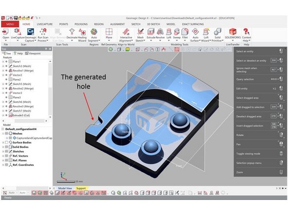
After the cutting your solid body should look like the one shown in the figure
-
-
-
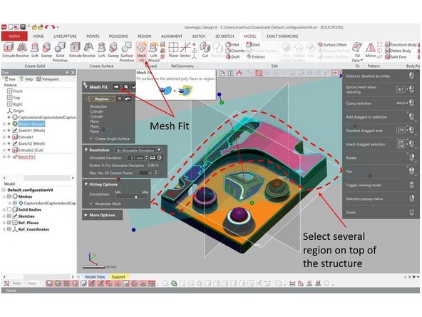
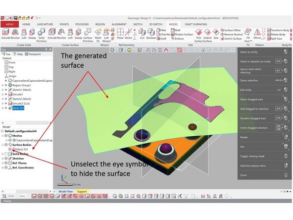
Use Mesh Fit option to create a Mesh Fit Surface
-
The Mesh Fit option can be found on the top window under Model
-
You need to un-hide the Region Group you created in the second step
-
Under Regions, select select several regions on top of the structure (See figure) as reference. This regions will not shown if Region Group is still hidden
-
Hit continue button and accept the result when you are done
-
If you feel that the surface is not a good representative of the top surface add more regions as reverence
-
You can hide the surface by un-select the eye symbol on the bottom left window (See figure)
-
-
-
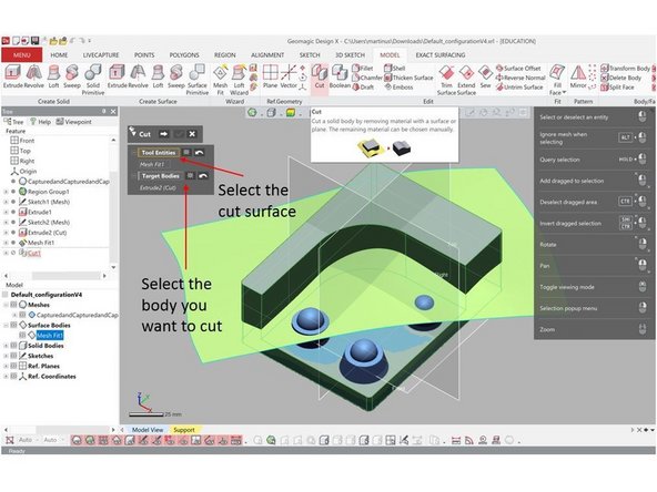
You can use the Cut option under Model in order to cut a body with respect to a surface
-
First, select the cut surface under Tool Entities (You need to select the surface you have generated in the previous step)
-
Second, under Target Bodies, select the body you want to cut and go to the next step (Hit the arrow button)
-
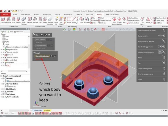
Then you will be asked to select which bodies you want to keep. Select the bottom body as shown in the figure
-
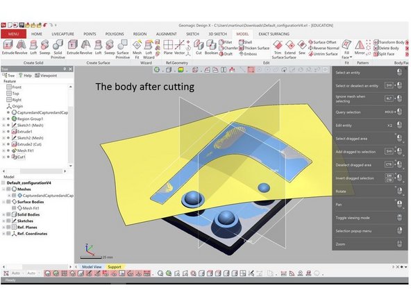
Your geometry after cutting should look like the one shown in the figure
-
-
-
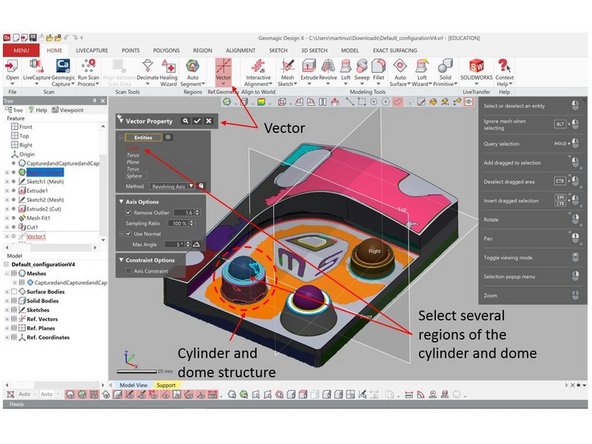
Now we want to create a solid body that represent the cylinder and dome structure (See figure)
-
Before we can create the body, we need to create a vector in the center of the cylinder and a plane that crossing the center of the cylinder
-
The vector can be created by using Vector feature at the top window under Home
-
Under entities, select several regions of the cylinder and dome
-
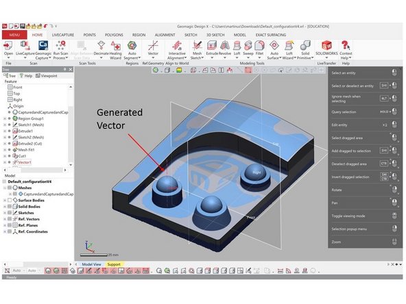
A vector will be generated at the center of the selected regions
-
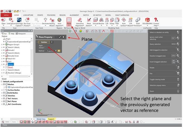
The plane can be created by using Plane feature at the top window under Home
-
Under entities, select the right plane and the previously generated vector as reference
-
A plane will be generated crossing the center of the cylinder and dome structure
-
-
-
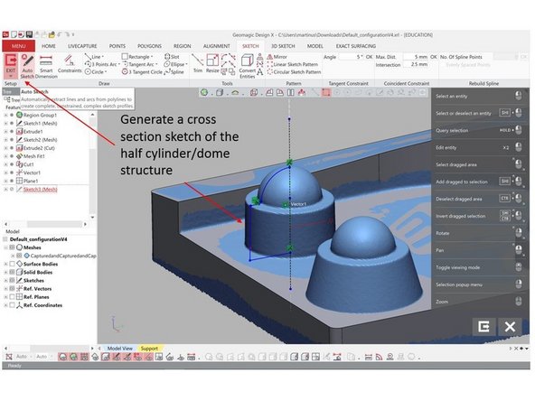
Use Auto Sketch feature (As explained in step 4) to generate a cross section sketch of the half cylinder and dome structure
-
Use the previously generated plane as the base plane for the sketch
-
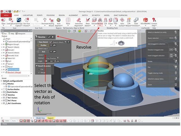
Use the Revolve feature under Home to generate the cylinder and dome body
-
Use the previously generated vector as the axis of rotation
-
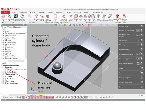
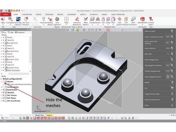
You can clearly see the newly generated cylinder and dome body by hiding the Meshes (Unselect the eye symbol next to Meshes on the lower left window)
-
-
-
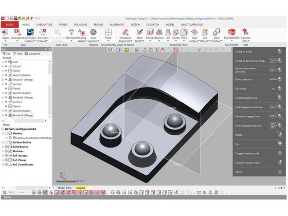
Repeat step 9 and 10 to generate the other two cylinder and dome bodies
-
At the end of this step you should have a body that look similar to the one shown in the figure
-
-
-
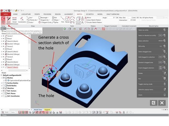
Now we want to create the hole like structure in the body (See figure)
-
First, generate a cross section sketch of the hole
-
For the sketch you can either use the front plane or generate another plane on the base of the hole
-
Use extrude cut feature to remove the material and generate the hole (See step 6 for more detail)
-
Use your judgement and sense on how much the extrusion distance
-
You should have a hole structure as shown in the figure
-
-
-
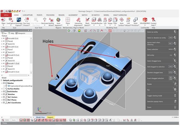
Repeat step 12 to generate the other holes
-
At the end of this step you should have a body that look similar to the one shown in the figure
-
-
-
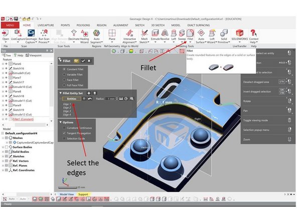
You can add fillet into the edges by using Fillet option under Home
-
Select the edges you want to add the fillet and set the fillet radius
-
Hit the ok button when you are done
-
At the end of this step you should have a body that look similar to the one shown in the figure. You can hide the mesh by un-selected the eye symbol next to it on the bottom left window
-
-
-
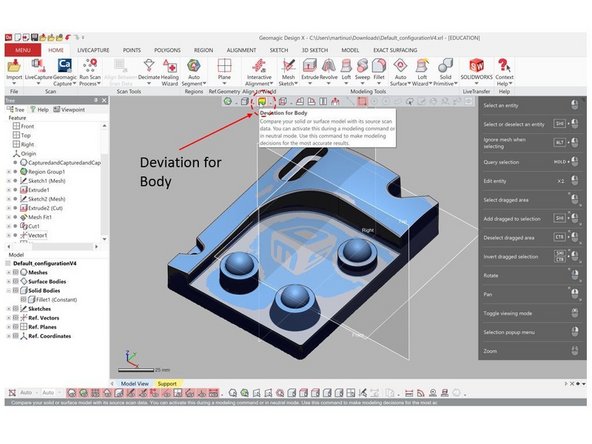
Geomagic Design X has a build in feature to calculate the deviation between the scan result and the converted geometry
-
Select Deviation for Body from the top window (See Figure)
-
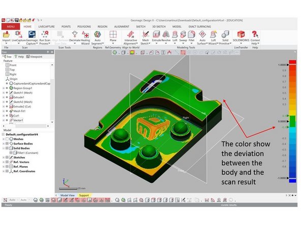
The color show the deviation between the body and the scan result
-
You an use this as a guideline if the converted geometry is acceptable
-
-
-
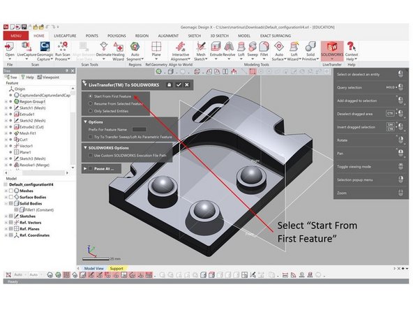
The generated body can be transferred into CAD software such as Solidworks, Creo, or NX. For this training we will transfer the body into Solidworks
-
You need to have the CAD software installed in the PC. If you want to transfer into Solidworks, you need to have Solidworks installed on the PC
-
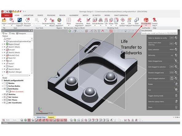
To transfer the body, use the LifeTransfer feature from the top window under Home
-
Select Start From First Feature as you want to transfer all of the feature you have created before
-
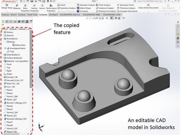
Geomagic Design X will automatically call Solidworks and recreate all of the feaure that you have generated (Enjoy the show)
-
You should have an editable Solidworks file in hand with all of its feature (Extrusion, extrude cut, etc.)
-


Congratulation you have learn the skill needed to convert 3D scanning result into editable CAD model.
Congratulation you have learn the skill needed to convert 3D scanning result into editable CAD model.