
Introduction
Often, multi-view engineering drawings form a key component of the material reviewed when evaluating a design for manufacturing. This guide overviews the process of creating an engineering drawing, and the tools available to annotate it properly.
-
-
Fusion 360 enables the creation of drawings directly based on a design. This bracket for a table comprises the demonstration part for this guide.
-
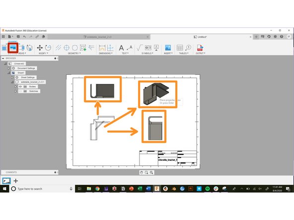
To open a new drawing, navigate to the workspace toggle, and select drawing from design
-
This will open a drawing creation window
-
In the drawing creation window, select the type of feature to draw (full assembly or only selected components)
-
Select the parameters of the drawing sheet
-
Hit Okay to open the new drawing
-
-
-
After finishing with the Drawing from Design window, a new drawing workspace will open
-
The new workspace starts with the base view feature already open
-
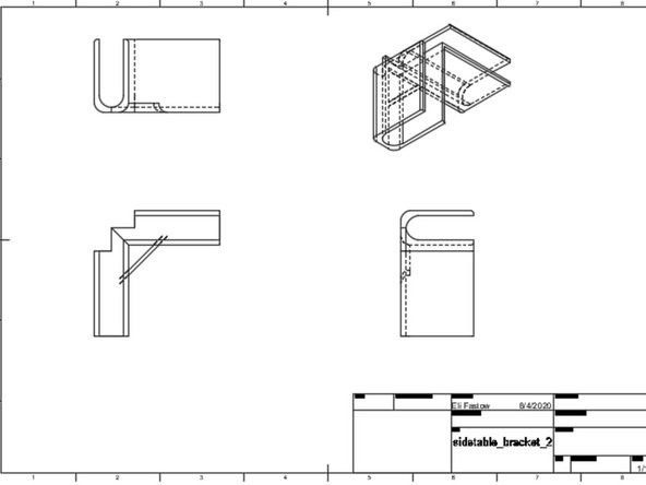
The base view is just a depiction of the part from one face or angle. The full drawing consists of a base view and several projected views, typically capturing the design from the front, top, right, and isometric views
-
Click in the drawing sheet to place the base view
-
Use the base view window to toggle to appearance settings and scale
-
Select the edge visibility. Options allow for making hidden edges or threads visible or invisible.
-
-
-
Use the projected view tool to create the rest of the perspectives on a design in a multi-view engineering drawing.
-
Select the Projected Views button in the toolbar
-
Select the base view, then drag and click to create new projected views
-
Create enough new views to depict all of the details on a part. This typically requires a front, top, side, and isometric view
-
Hit the enter key to exit the projected view tool
-
-
-
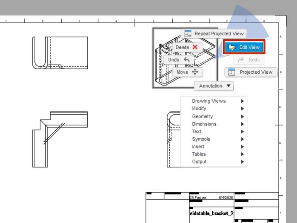
To edit a projected view, right click on the view then select "Edit View"
-
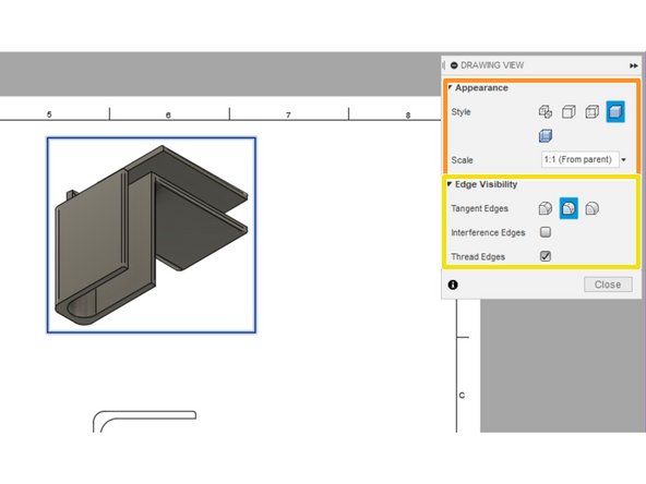
This opens up a Drawing View setting window. Use this window to edit the appearance and scale.
-
This window also includes edge visibility settings
-
-
-
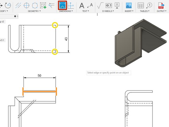
Adding accurate dimensions is essential to a complete multi-view drawing
-
Click on the smart dimension button on the toolbar to create dimensions
-
Smart dimensions can automatically recognize individual features. For example, selecting a line prompts a length dimension.
-
Selecting two points prompts a length dimension between them. Selecting three points prompts an angle.
-
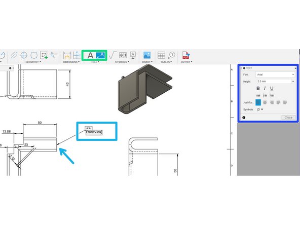
To create an annotation, select either the text or leader text button in the toolbar.
-
Select the object to annotate if using leader text then type the annotation.
-
Format the text with the pop-up text window.
-
-
-
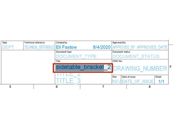
Double click on any of the text in the properties table at the bottom right corner of the sheet to edit.
-
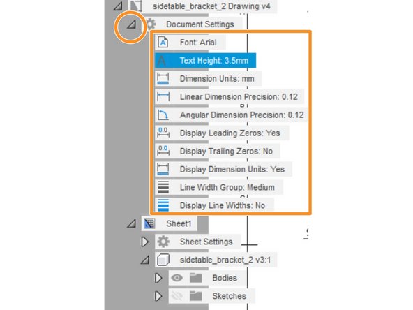
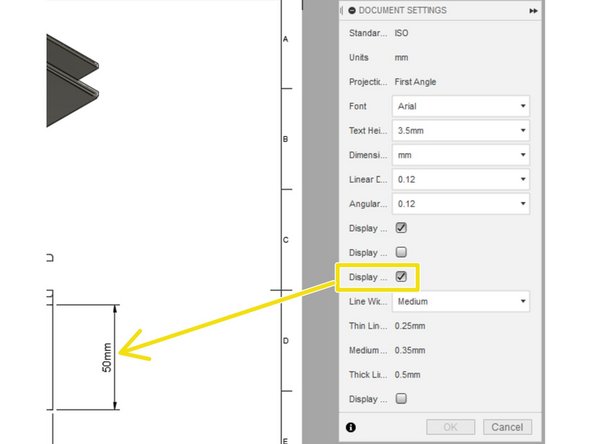
To edit any of the global document settings, open the Document Settings menu in the feature tree and double click on any of the settings
-
This opens the document settings menu
-
Use the document settings menu to change any global text or display settings. For example, we used this menu to add units to all dimensions
-


Cancel: I did not complete this guide.
One other person completed this guide.