-
-
Create a new sketch on your part in CAD.
-
Include the 3d geometry of the top face that will be cutting out.
-
Save the sketch as a DXF.
-
-
-
First Select PROG IN/OUT to get to get to the file selection screen
-
Select your file in the list of files. You may need to navigate between directories if it is on a different USB drive.
-
Select "Open" in order to load your DXF file into the converter.
-
After opening a DXF file it will show the start splash screen again. Select PROG in order to continue to the next steps.
-
-
-
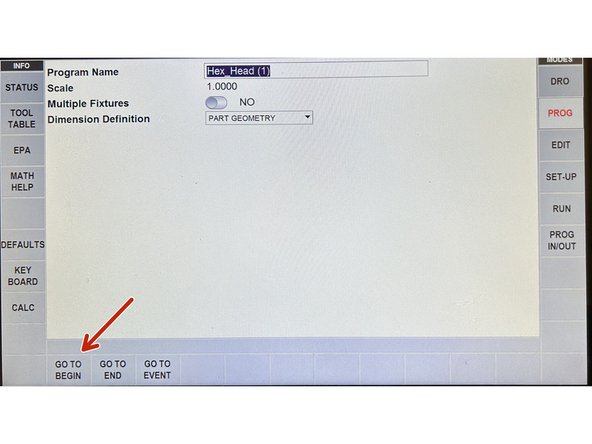
You may not be able to see your part at first. Select TOGGLE BGCOLOR in order to swap the colors and make it more visible.Select GO TO BEGIN to enter the DXF programming mode.
-
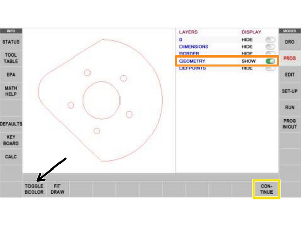
You may not be able to see your part at first. Select TOGGLE BGCOLOR in order to swap the colors and make it more visible.
-
Ensure that only the part geometry is visible. This will most likely be when just GEOMETRY is checked but depending on how it was exported you may not have these options.
-
If you had to remove lines from your DXF with the step above the DXF may be small on the screen. You can select FIT DRAW in order to make the DXF fill more of the view.
-
Select CONTINUE to begin programming your part.
-
-
-
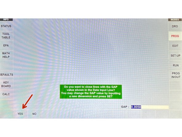
When it prompts you whether you would like to close lines with GAP value select YES.
-
Ensure that the GAP Value is set to 0.0050!
-
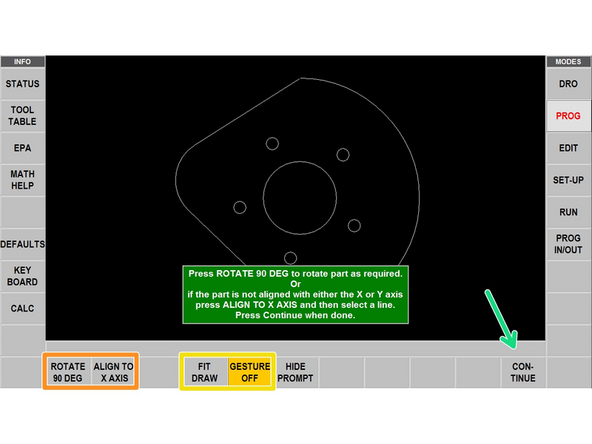
Your part should now be visible on the screen and will display the orientation that it has loaded in.
-
To rotate your part in 90-degree increments you can use ROTATE 90 DEG or you can ALIGN TO X-AXIS by selecting a line you want to be aligned and then selecting it a second time.
-
You can pan the view by dragging inside the view and zoom by pinching inside the view. To get back to the default view select FIT DRAW. To turn off panning/zooming select GESTURE OFF/ON.
-
When the dxf is in the correct orientation relative to the actual part in the clamp select CONTINUE
-
-
-
The zero is indicated with the red dot. If the absolute reference is off of the part, the dot will not show up.
-
The DXF will load with a default zero at the center of your part. You have 3 options for changing this:
-
A: Select two lines/arcs (no circles) and the absolute reference will be set to where the two intersect.
-
B: Select near the desired end on a line or arc to set the absolute reference to this end. (no circles)
-
C: Select an arc or circle and the absolute reference will be set to the center of the selected geometry.
-
OFFSET ABS 0 will allow you to shift the zero point selected by some offset from it's current position.
-
Select CONTINUE once the absolute reference is set. This is also where you will have to center the mill when you're ready to make the cut so choose a place that's easy to zero on.
-
-
-
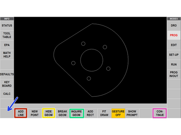
Before adding events the dxf lines can be edited to make last-minute additions
-
ADD LINE: Selecting a line or arc close to an end point and the same to another line or arc will create a line between the end points.
-
HIDE LINE: Click on a line or arc to hide it in the DXF.
-
INQUIRE GEOM: Clicking on geometry will present you with dimensional data on it.
-
UNDO: Undos your last action.
-
Once the DXF looks good select CONTINUE
-
-
-
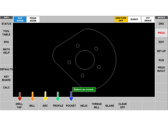
The 3 steps to setting up events are: picking the event type, picking the geometry, and filling in the additional event info.
-
-
-
Each event has a specific purpose and their own separate event details that have to be programmed:
-
DRILL TAP: Drill, tap, or bore a hole at the selected X,Y for the center of a hole or a point. Select all similar holes when selecting events so that programming the first will update all of them. **Only feeds the Z, X and Y are fixed during event.
-
MILL: Converts a straight line into a straight path from the start of the line to the end. Select the end of the line that you want it to start from.
-
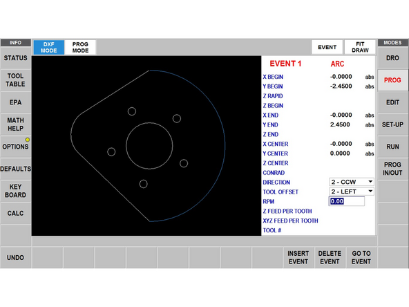
ARC: Converts a curve into a arc path from the start of the line to the end. Select the end of the line that you want it to start from.
-
PROFILE: Select a series of lines to make a connected path between all of them. The first line selected determines where the event starts and the next line selected determines the direction.
-
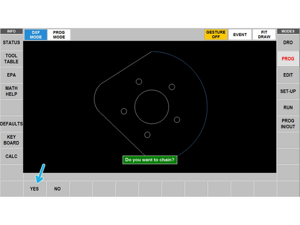
Chaining: When prompted if you want to chain select YES. This will
-
POCKET: Geometry must be selected that encloses a shape (starts where it ends). The first line selected determines the starting point, the second determines direction (CW or CCW).
-
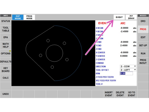
Once all of your events are set, press EVENTS in the top right to begin programming the events.
-
-
-
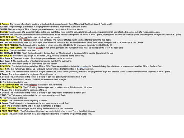
The third image is a description of the most common event prompts and what they mean. For more details you can access the full RMX Programming guide.
-
For each event, you will need to enter in additional information before the cut is made. It's crucial that you keep the RPM and feed rates at a reasonable level or you could damage your part or the end mill.
-
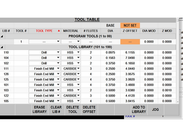
ADD MORE DETAILS FOR SPECIFIC CASES AND ADDING TOOLS FROM TABLE
-
-
-
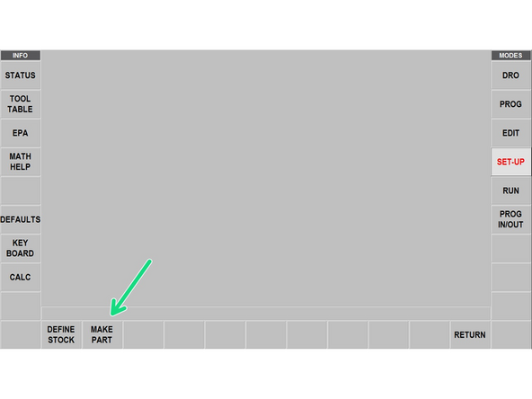
Once you are done programming events, select SET-UP. This will allow us to both generate the actual path and verify that everything looks good.
-
Select TOOL PATH to begin generating the actual path. Depending on the number of events and size of the part this may take a while.
-
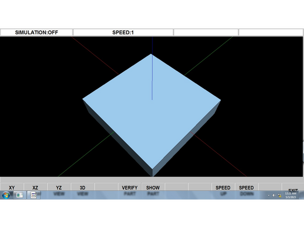
To verify that the path will actually cut the desired shape you can choose VERIFY PART which will bring up a 3D shape to view the path and what is cut out. (Can be seen in 3rd image). You may select MAKE PART to view the 3d shape and DEFINE STOCK to bring up a dialog to define the size of your stock for a correct reference.
-
-
-
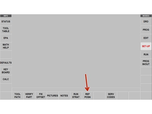
Select REF POSN to bring up the reference position dialog.
-
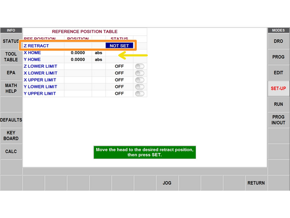
This is a very important step because messing it up could result in you crashing the trak into your part without running the mill or result in your parts coming out to the wrong depth.
-
Z-RETRACT: This is where the head will go when it is done with the cut and for tool changes. You will jog the Z-Axis to where you need it and then press ABS SET to set it there.
-
X HOME and Y HOME are where the saddle go when there is a tool change or at the end of the program. You shouldn't need to change these from 0,0
-
-
-
BEFORE you begin running the program, ensure that in DRO mode you set the zero of the trak to the zero you defined while programming the part and set the Z zero of the part to the surface of the piece.
-
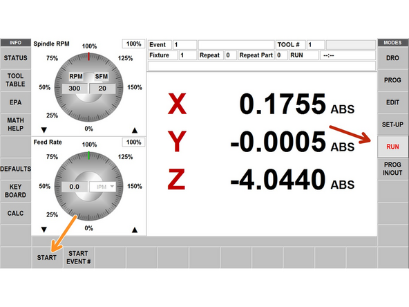
Once the zeros are properly set, select RUN. This will bring you to a different menu from the DRO that will allow you to begin running your part.
-
For almost all use cases you will select START to begin your part.
-
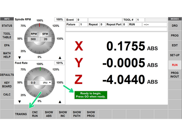
Select TRAKING in order to run through the program using the handwheels. Select CNC RUN to run through it programatically. You will be prompted to hit GO when ready to begin.
-
The X axis handwheel will be a coarse control while Y axis is more fine. You should primarily be using the Y-axis. Clockwise moves forwards in the program. Counterclockwise moves backwards in the program.
-
Cancel: I did not complete this guide.
2 other people completed this guide.


