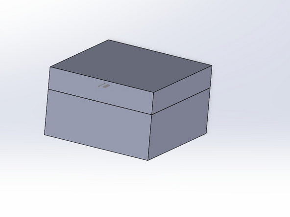
-
-
This method should be used with complicated geometry. recommend using this method on imported designed from public library.
-
-
-
Once you have your part the next step is to perform a draft analysis.
-
Draft analysis makes sure that there is an adequate draft angle on the part. draft angle ensures that the part gets ejected with out struggle or causing damage to the part.
-
The draft analysis feature is located in the mold tools tab.
-
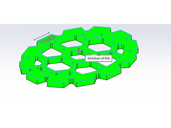
Once you've selected the draft analysis feature. select a positive face (highlighted green) that will serve as a zero for your draft analysis.
-
The zero is a Geometric reference in reference to the base of the mold.
-
The yellow faces represents all the faces that require added draft.
-
-
-
Now that we have determined the faces that need a draft angle the next step is to add draft angles to those faces.
-
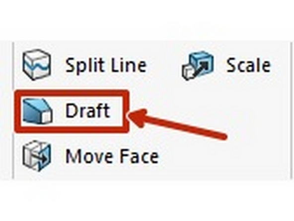
Select the draft feature which is located in the mold tool tab.
-
Select all the faces that required a draft angle and apply a draft angle that works for you part (usually between 1-3 degrees).
-
Once the draft angle has been applied to the faces. the draft analysis will show them as green meaning that they no longer require draft.
-
-
-
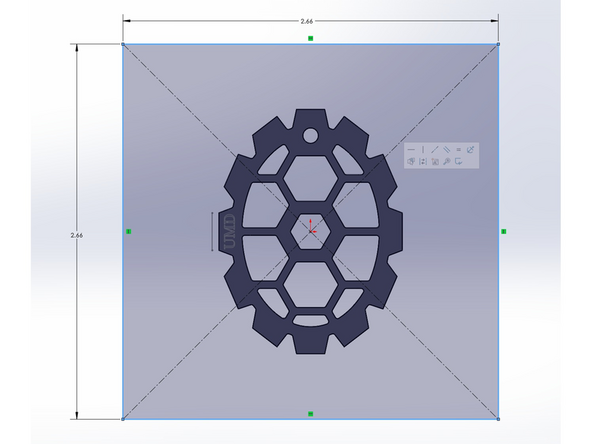
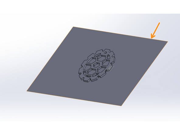
Sketch a boundary around the part bake sure this boundary larger than the dimensions of the mold as this will be used to split side A and B of the mold.
-
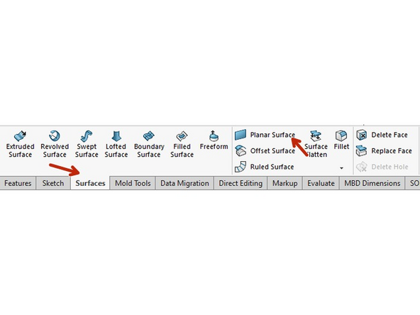
Once the boundary has been sketched use the planar surface feature located in the surface feature tab.
-
once the feature has been applied a think surface will appear.
-
-
-
The next step is to create the mold sides
-
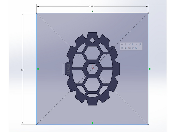
Sketch a rectangle around the part which will be the size of the mold. in the case shown we will be making a 4 cavity mold the the mold dimensions need to be 5.31x5.31 meaning that 1/4 of the mold will have dimensions of 2.655 x2.655 as shown in the first picture.
-
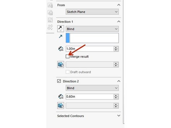
Extrude the A side and B side making sure not to merge results that way the part is still present
-
-
-
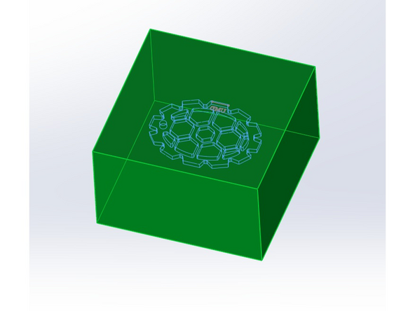
In this step you are creating the Cavity image by subtracting the part from the main body extrusion created in teh last step
-
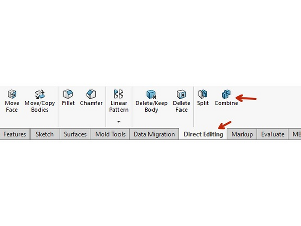
Select the combine feature located in the direct Editing tab
-
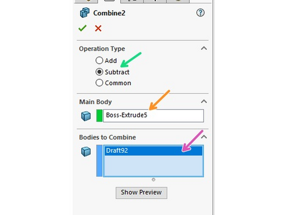
Select the subtract operation type
-
For the main body select the extrude mold body from step 5.
-
For the bodies to combine select the part body easily found in the solid bodies drop down.
-
now you can see in the third image, the the cavity image in the shape of the part.
-
-
-
The next Step is to split the bold intro A and B sides using the split feature.
-
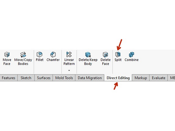
Select the Split feature located in the direct editing tab.
-
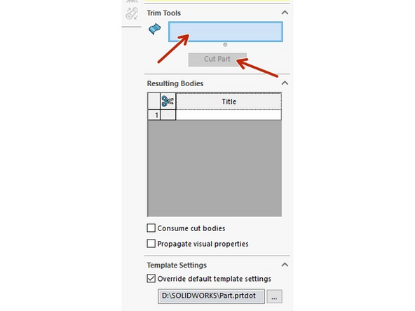
For the the trim tool use the surface plan from step 4 as you trimming tool. then price the cut button. this will use the surface as a cutting tool to cute any body in contact with the surface
-
Almost done!
Finish Line


