Introduction
The Desktop Metal Shop is a metal 3D printing solution by Desktop Metal which utilizes a binder jetting process. It is best suited for batch metal printing, and the parts are ready for prototyping, end-use or further post-processing through any traditional techniques. The parts produced are solid metal and have a consistent surface finish.
“It works a bit like inkjet document printing, but instead of jetting drops of ink onto paper, the print head jets microscopic binder droplets onto a fresh bed of metal powder. Once baked, this holds parts together long enough to excavate and sinter them into fully dense metal parts. “
Learn more about the capabilities and technology supporting the Desktop Metal Shop system.
Images by: Terrapin Works and Desktop Metal
-
-
The DMS system is a high volume metal 3D printing solution
-
Fully solid metal parts, with high repeatability and good mechanical properties
-
No post-sinter processing necessary - no support and easy to remove from the build area
-
Lower cost than other, laser-based processes
-
High accuracy and resolution
-
-
-
DMS uses Binder Jetting, which is powder bed based process:
-
A piston and roller distribute a fine layer of powder in the build area
-
An COTS inkjet head deposits binding agent in the desired geometry using 70000 micronozzles
-
This process repeats several hundred (or thousand) times to define 3D geometry
-
The entire build box is then cured in an oven to cure the parts to a "green" state
-
The build box is excavated to remove the green parts from loose powder, and all loose powder is recycled back into the process
-
The green parts are sintered at ~1400 C for several hours in order to fuse the green parts into solid stainless steel
-
-
-
Design guidelines for the DMS system can be found on the category page
-
1600 dpi resolution in XY
-
40-100 micron resolution in Z
-
17-4 PH Stainless Steel part with maximum wall thickness of 1 inch
-
Tunable layer parameters
-
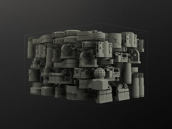
Dozens or hundreds of unique parts can be printed in a single batch
-
-
-
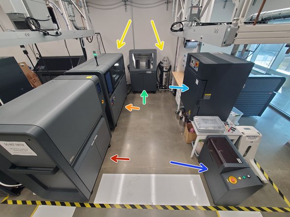
DMS Furnace
-
DMS Printer
-
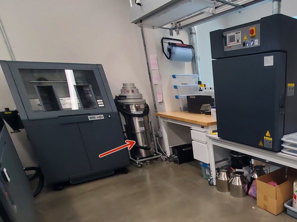
2 Immersion, explosion-proof vacuums
-
DMS Powder Station
-
DMS Drying Oven
-
DMS Blender
-
-
-
There are two utility cabinets on the furnace
-
The left utility cabinet holds gas canisters that could be used for the studio system, but is useless for the shop system
-
The right utility cabinet contains the binder trap and compressor (where oil can be filled)
-
The furnace door can only be opened when the system is vented, by the up and down arrows on the side
-
The touchscreen is on the front right, and can be used to perform all standard machine functions
-
The e-stop is on the front right, and can be used to shutdown the machine during emergencies
-
-
-
There are two exhaust pipes which come out of the back of the furnace
-
These feed into tee-connectors, for condensate to collect in the clear plastic bottles
-
The condensate bottles should regularly be checked to see if they need to be emptied
-
The other end of the tee should feed into an external exhaust line
-
There is a VCO type fitting connection for external gas on the back of the furnace
-
The external gas used is hydrogen balanced argon (3% hydrogen)
-
The gas pressure can be adjusted with the regulator and briefly loosening this fitting to allow gas to flow, or by running a Purge Gas Line operation on the furnace
-
-
-
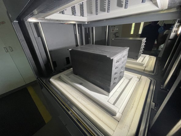
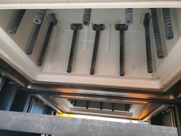
The furnace operates using several powerful infrared heaters, which heat the retort in full vacuum
-
These heaters are fragile and expensive, DO NOT touch them
-
The retort is made out of graphite, and serves to direct forming gas in laminar flow over the parts inside
-
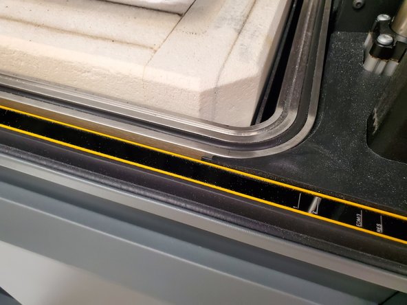
There is a steel bell which serves as the top part of the vacuum chamber, and must seal to the lower portion with the O-ring shown
-
The O-ring shown should be maintained and kept clean, but should not be exposed to any fluids besides DI water when cleaning
-
The white insulation is silica based - proper PPE should be worn whenever the chamber is open
-
-
-
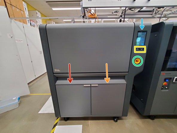
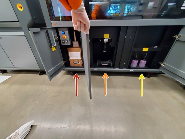
There are three utility cabinets on the DMS printer
-
The left utility cabinet holds the binder cartridge and fines jar
-
The center utility cabinet holds the overflow keg
-
The right utility cabinet holds the waste overflow containers
-
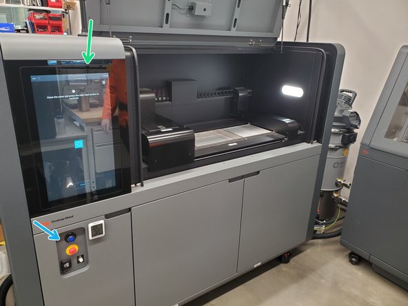
The touchscreen is the main interface with the machine
-
E-stop, white power on button and blue reset button are located below the display
-
-
-
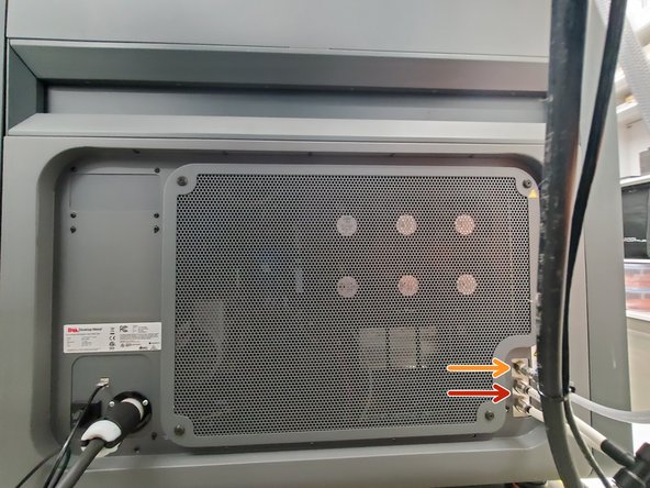
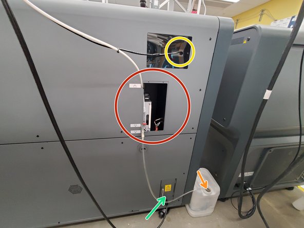
The water inlet (for the humidifier) goes into the rear panel
-
The small rear panel has to be removed to replace the tube or service the humidifier
-
There is a water overflow which must go into an overflow bin
-
The ethernet connection goes into the rear panel
-
The power cord and main breaker for the machine are behind the electrical panel
-
-
-
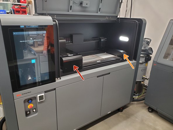
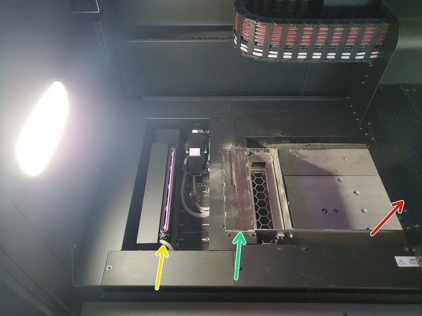
The print area is humidity controlled and should not be open without reason
-
Both carriages inside the printer area are disabled when the printer door is open
-
The left carriage is the printhead carriage
-
The right carriage is the spreader carriage
-
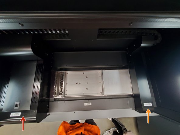
The printhead cap seals and increases the longevity of the printhead in between prints
-
The spit pad essentially catches excess binder that may be left near the printhead or on the printhead nozzles
-
-
-
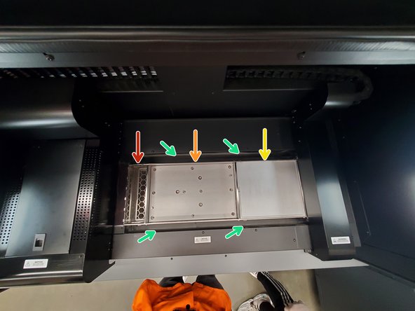
The powder overflow chute and tray directs and filters powder that is spread over the edge of the print area and allows it to fall into the overflow keg
-
The build area is where powder is spread onto and binder jetted down on top of in order to create part geometry
-
The powder piston holds metal that will be used during the print, incrementally raising and exposing more powder to the spreader carriage
-
The area surrounding the print area and powder piston are used to control and catch any extra powder
-
-
-
One vacuum is run throughout the entire print, and is powered by compressed air
-
This vacuum MUST be grounded with the grounding clamp whenever in use
-
The other vacuum is run during any other powder processing tasks, such as cleaning parts, cleaning the printer, or transferring powder (this one is powered with electricity)
-
Both vacuums have a separable bottom, and the vacuum bags reside here
-
The vacuum bags are immersed in water, which must be properly disposed
-
-
-
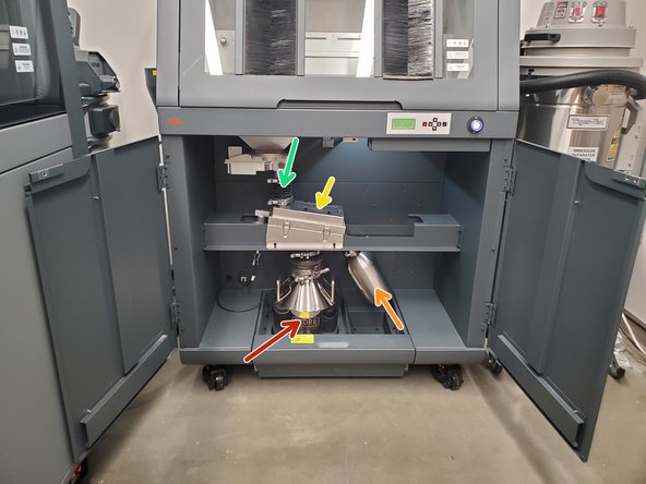
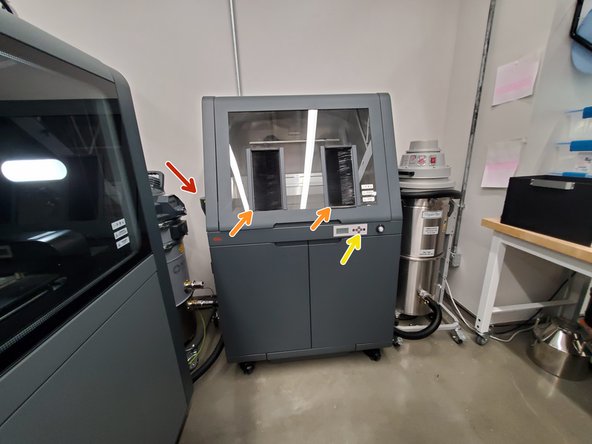
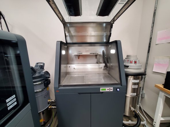
The powder station is primarily used to excavate parts and participate in the post-print process
-
There is a lower utility cabinet, which holds:
-
Blend keg
-
Waste jar
-
Sieving screen
-
Dosing chute
-
This area should be kept as clean as possible
-
-
-
There is a cyclone separator on the side of the powder station, with a fines jar and vacuum inlet
-
The vacuum and fines jar should always be installed when using the powder station
-
The upper chamber of the powder station has brushes in the door for the operator
-
Always hit the door a few times and allow metal powder to settle before opening
-
The station should never be used to excavate parts with the door open
-
The main interface on the powder station is the screen and arrow keys up front, and the white power button to the right
-
-
-
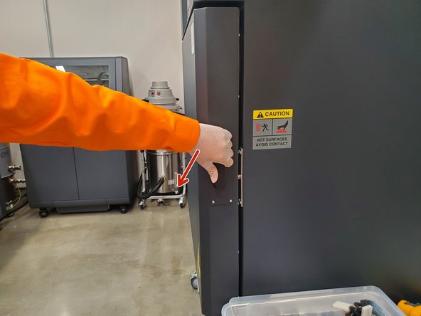
The handle of the drying oven turns counter clockwise to open
-
The drying oven should NEVER be opened without proper PPE
-
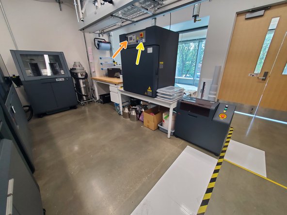
The main interface is up front, and has several buttons to interact with the menus
-
E-stop and power switch are to the right of the main interface
-
The exhaust lever is at the back of the drying oven
-
-
-
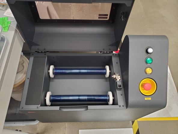
The blender has a single powered roller and an idler roller
-
The lid also has an interlock, so it cannot be run with the lid opened
-
There is a one button, status light and e-stop button on the right
-

