
Introduction
The pin table offers a method for lifting cutting materials completely off of the vector grid to perform cutting without any flashback (i.e. there is no "burn" marks on the back of the piece).
The pin table is 12" x 12" and can only support moderately heavy materials and should only be used for pieces where it is absolutely integral that no "burn" marks are on the finished piece.
-
-
The pin table can be found in the cabinet next to the Epilog.
-
The pin table should only be used when necessary.
-
The pin table can only support work pieces that are 12" x 12" maximum and only has 30 pins available to lift up your work piece.
-
Due to how it has to be aligned in the software, if "burn" marks on the back of cuts are okay, then the pin table does not need to be used.
-
-
-
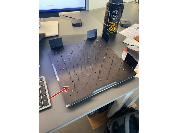
As seen here, the pins can be oriented in any way shape or form needed to conform to the work piece. To install/remove pins, simply push them in the circles or pull them out. There should be a moderate amount of resistance when doing so.
-
The parts lifter is a convenient way to remove any debris made from cutting with the pin table. Simply lay the parts lifter on top of the pin table assembly to install.
-
To use the pin table, just lay your work piece on top of the pins in an orientation that avoids cutting over top of the pins.
-
-
-
Be careful of using the autofocus feature on the pin table, your workpiece may flip over or be moved when doing so.
-
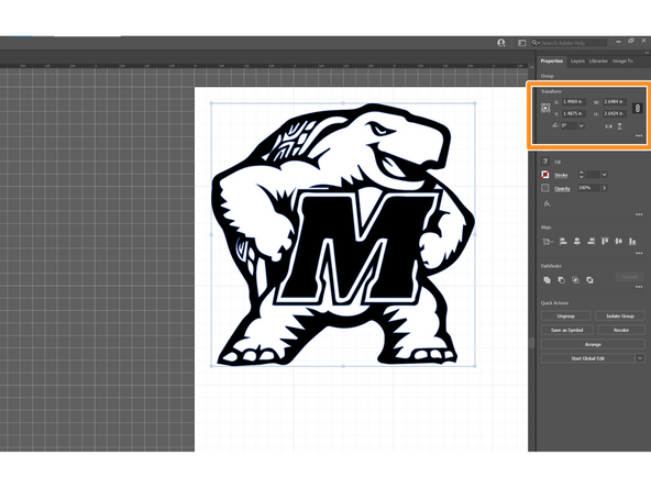
The grid on the Pin Table is 1" x 1", to show a grid in Adobe Illustrator go to View > Show Grid and then press ctrl + r to show the rulers on the margins.\
-
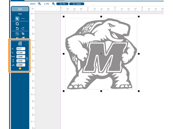
Unfortunately, in the Epilog Software, there is no way to show a grid overlay, so sizing your pieces the same proportions as that seen in Illustrator is the only way to avoid cutting overtop of the pins.
-
In this case, in Illustrator I made the design roughly 2.6" x 2.6" using the grid to avoid the pins at the 1" x 1" pattern marks.
-
Then in the Epilog software, I used the same x & y position as well as scaling as in Illustrator to line up the piece in the exact same position.
-
Always make sure to check with the physical rulers in the machine as well to confirm you will not be cutting overtop any pins!
-


Refer to the user manual in the cabinet next to the Epilog for any further details.
Refer to the user manual in the cabinet next to the Epilog for any further details.
Cancel: I did not complete this guide.
3 other people completed this guide.