-
-
Before we start make sure you have the main components to use the multimeter
-
Positive test lead
-
Negative test lead
-
-
-
The negative test is inserted in the black colored terminal
-
To measure current, the positive test lead must be inserted in the left, red terminal
-
To measure everything else, the positive test lead must be inserted in the right, red terminal
-
-
-
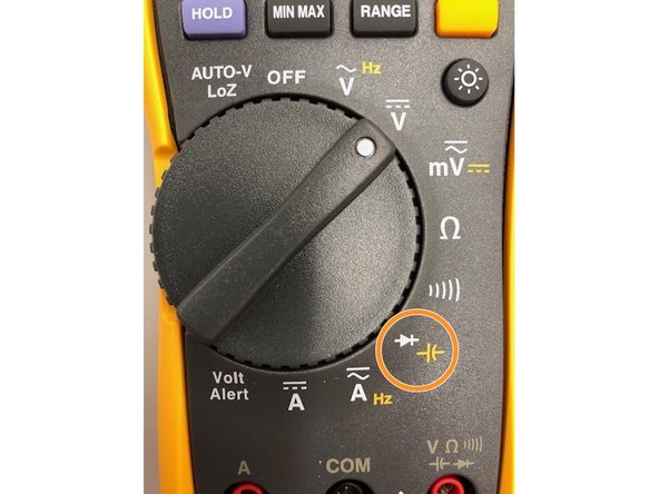
There are multiple positions for the rotary switch to be set. The table gives a brief summary on what each setting does
-
-
-
There are four buttons on the Fluke 117 Multimeter:
-
HOLD: Turns on all display segments
-
MIN MAX: Disables beeper. "bEEP" is displayed when enabled
-
RANGE: Enables low impedance capacitance measurements. "LCAP" is displayed when enabled
-
Orange button: Disables automatic power-down ("Sleep mode"). "PoFF" is displayed when enabled
-
Brightness: disables auto backlight off. "LoFF" is displayed when enabled
-
-
-
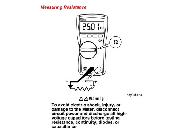
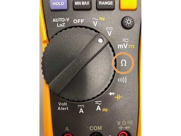
To measure resistance, set the knob to "Ohms" and place the leads on either side of the circuit you want to measure resistance from
-
Set the Knob to the Omega symbol
-
-
-
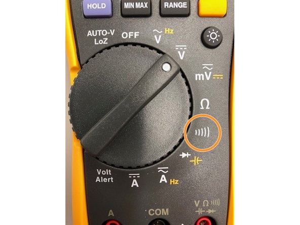
To measure continuity, set the knob to the symbol that looks like waves. Place the leads on either side that you want to test for. If there is a beep then there is a continuous current , if not, then there is an opening or short in the circuit
-
Set the knob to the "wave" symbol
-
-
-
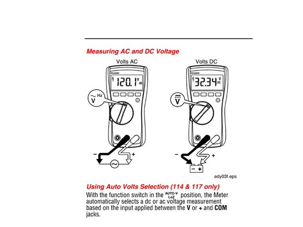
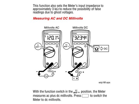
To measure voltage, set the knob to "V". The wave symbolizes AC and the line followed by a dashed line symbolizes DC. Set the leads on either side to measure the voltage of that portion of the circuit
-
To measure millivolts, set the knob to "mV"
-
AC Voltage
-
DC Voltage
-
AC Millivoltage. Press yellow button for DC Millivoltage
-
-
-
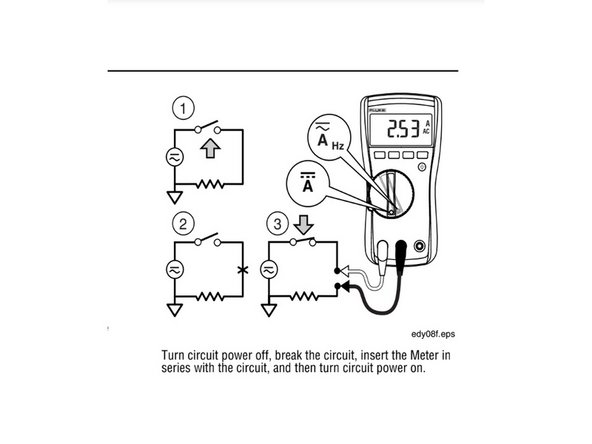
Use the proper terminals, switch position, and range for your measurements
-
It is good practice to follow the three steps shown in the image. Set the knob to "A", and the same symbols apply for AC and DC current
-
DC Current
-
AC Current
-
-
-
Set the knob to the symbols shown to measure capacitance
-
Switching the position of the leads for other measurements will only change the sign. For capacitance it is important to have the negative lead placed on the charging side and the positive lead on the discharging side
-
Press the yellow button and switch to symbol shown for capacitance
-
-
-
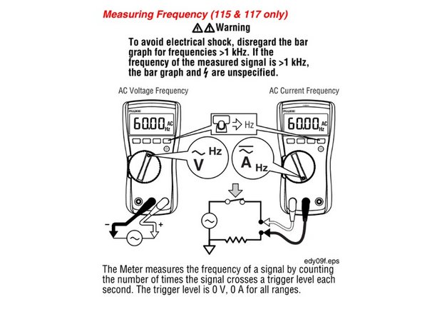
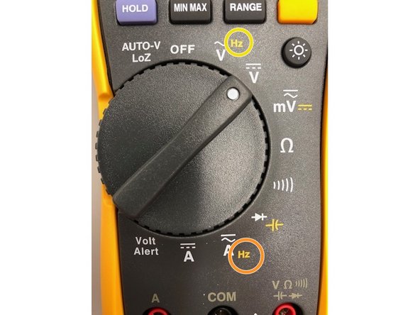
To measure voltage frequency, set the knob to "V (AC)" you will also see the "Hz" symbol
-
To measure current frequency, set the knob to "A (AC)" you will also see the "Hz" symbol
-
Press yellow button and switch to the AC Voltage position
-
Press yellow button and switch to AC Current position
-
-
-
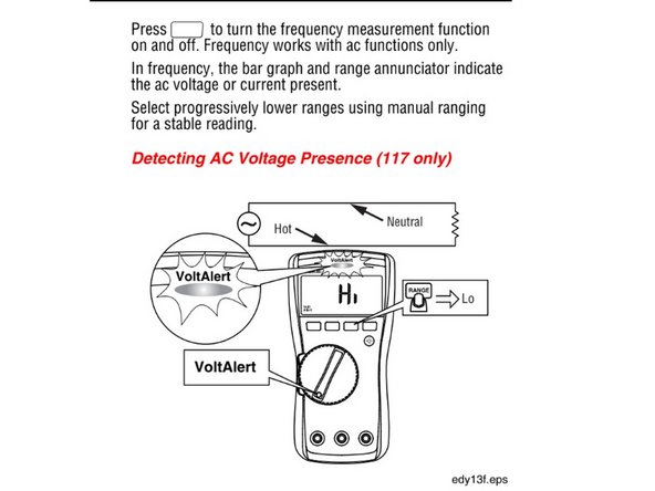
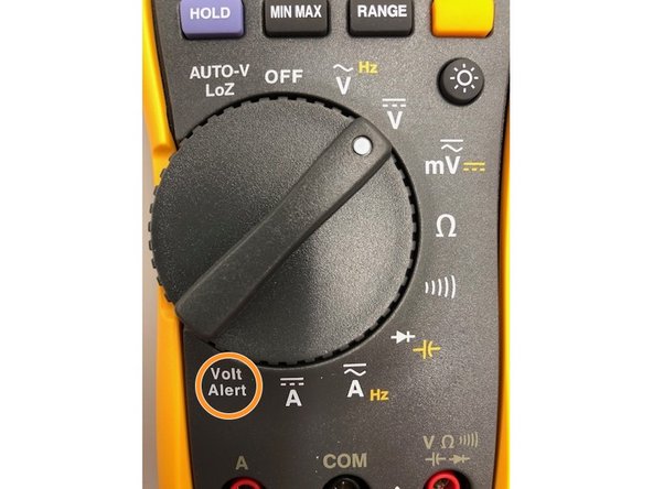
To detect the presence of AC voltage, place the top of the meter close to a conductor. The meter gives an audible as well as visual indication when voltage is detected
-
There are two sensitivity settings. The "Lo" setting used for various power cords, and the "Hi" setting which allows for AC voltage detection on other styles of recessed power connectors or sockets where the actual AC voltage is recessed within the connector itself
-
Switch to the Volt Alert position
-
-
-
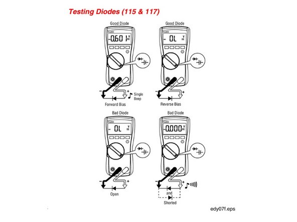
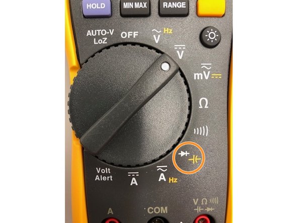
To measure diodes, set the knob to the symbols shown in the image
-
As seen in the image, a good diode will give an audible signal when measuring a forward bias diode and no signal with 0L for a reverse bias diode.
-
A bad diode will give no signal for a forward bias, and a long auditory signal for an open and shorted diode
-
Set knob to the diode symbol. DO NOT PRESS YELLOW BUTTON
-
-
-
The guide is finished! If you have any questions do not hesitate to ask Terrapin Works staff before performing measurement
-
Images and guides were taken and edited from the Official Fluke 117 Multimeter Manual: https://www.allaboutcircuits.com/test-me...
-