-
-
Here is the layout for what you will be using. There are three components:
-
Positive Test Lead (Red probe)
-
Negative Test Lead (Black probe)
-
Fluke 287 Multimeter
-
-
-
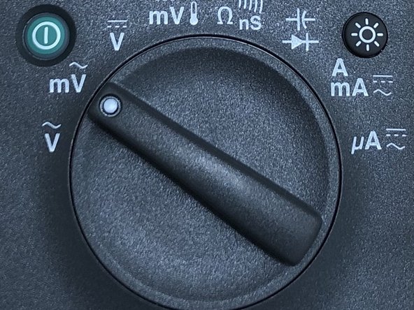
The multimeter knob is used to change what the probes will read. We will talk about each setting soon!
-
The power button turns it on and off
-
The arrows are used to navigate the menus of the multimeter
-
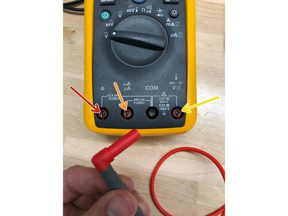
These are the different settings you can place the probes in. Where you will plug them in will depend on the desired units you want to be measured
-
Remember, black probe goes into black. Red probe goes into red
-
-
-
The red probe can be plugged into three different ports:
-
Measures in Amperes (A)
-
Measures in mill- and microAmperes (mA, uA)
-
Measures voltage, resistance, capacitance, and induction
-
-
-
There are several symbols on the rotary switch for different measurements
-
The chart goes into detail about each symbol on this model multi-meter
-
The Chart has extra symbols not included on this multimeter
-
The wave symbolizes AC (Alternating Current)
-
The solid line and dashed line symbolizes DC (Direct Current)
-
-
-
This table goes through the display of the 287 by briefly talking about each component
-
To read about each feature in more detail you can find it in the Fluke 287 User manual: http://assets.fluke.com/manuals/287_289_...
-
-
-
The table shown goes into each push button feature on the 287
-
-
-
The meter displays DC voltage as well as their polarity. The bar graph displayed is zero-centered and will fill to the right for positive readings and fill to the left for negative readings
-
The softkey labeled "menu" can be used to modify the basic DC voltage measurement
-
AC Voltage Position
-
AC Millivoltage position
-
DC Voltage position
-
DC Millivoltage position
-
-
-
To avoid possible damage to the meter or to the equipment being tested, disconnect circuit power and discharge all high-voltage capacitors before testing continuity
-
The meter uses three indicators for the absence and presence of continuity: a resistance reading, an open/short indicator, and a beeper
-
Continuity (waves) position
-
-
-
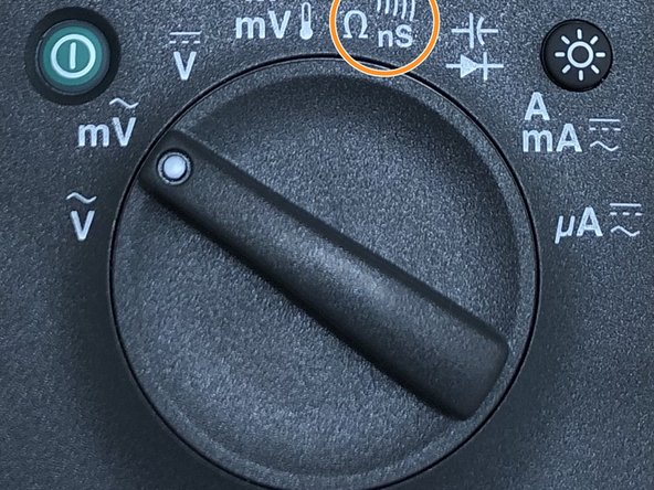
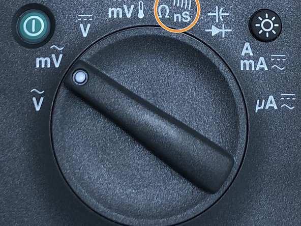
Conductance is the inverse of resistance, and is the ability of a circuit to pass current. High values of conductance correspond to low values of resistance
-
To measure conductance, position the rotary switch to the symbols shown in the image. Press the softkey labeled "nS"
-
To measure resistance press the softkey labeled "Ohms" (Omega symbol)
-
Resistance (Omega symbol) position
-
-
-
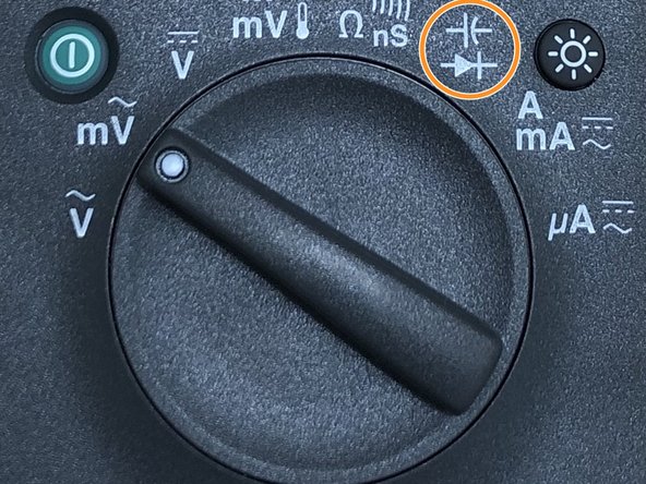
Use the diode test to check diodes, transistors, silicon controlled rectifiers (SCRs), and other semiconductor devices. The test sends a current through a semiconductor junction, and then measures the junction's voltage drop
-
To test a diode out of a circuit, position the rotary switch to the symbol show in the image. Position the two leads as shown in the image
-
If the display doesn't already indicate the meter is in the diode test function, press the softkey labeled "menu". Next, move the menu selector to the menu item labeled "Diode,Cap" and press the softkey labeled "Diode"
-
Diode/cathode position
-
-
-
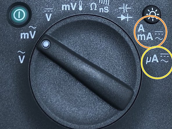
Current is the flow of electrons through a conductor. To measure current, you must open the circuit under test, then place the meter in series with the circuit
-
To avoid blowing the meter's 440 mA fuse, use the mA/uA terminal only if you are sure the current is less than 400 mA
-
Depending on the expected current from the circuit you are measuring, insert the leads as shown in the second image
-
AC/DC Amp and Miliamp position
-
AC/DC Microamp position
-
-
-
The guide is finished! If you have any questions do not hesitate to ask Terrapin Works staff before performing measurement
-
Images and guides were taken and edited from the Official Fluke 287 Multimeter Manual: http://assets.fluke.com/manuals/287_289_...
-