Introduction
The Stratasys Fortus 400mc is an industrial grade FDM printer intended for small scale manufacturing of functional parts. This guide will give you a brief overview of the machine’s strengths, a description of the physical layout of the printer, and instructions on how users can interface with the Fortus.
-
-
Consistent Quality - A TIGHTLY CONTROLLED print environment means that all parts have CONSISTENT QUALITY
-
Functionality - Fortus parts aren't always the prettiest; the focus is on making FUNCTIONAL products
-
Advanced Materials - The Fortus can run materials with EXCELLENT MECHANICAL, THERMAL, and CHEMICAL PROPERTIES which include PC, PC-ABS, PPSF, Ultem 9085, and more
-
Large Volume - A build volume of 16 x 14 x 16 inches provides enough room for MEDIUM to LARGE prints
-
Marfa Approved
-
-
-
Top Door - Houses the PRINT HEAD
-
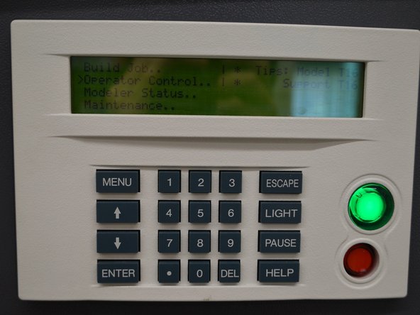
User Interface - ALL operations including maintenance, calibration, and running jobs are done through the interface
-
Oven/ Oven Door - This is where parts are printed
-
Canister Bay/ Canister Bay Door - This is where FILAMENT is loaded into the machine along with useful TOOLS for performing varying tasks
-
Upper Side Panel (left & right)
-
Lower Side Panel (left & right)
-
-
-
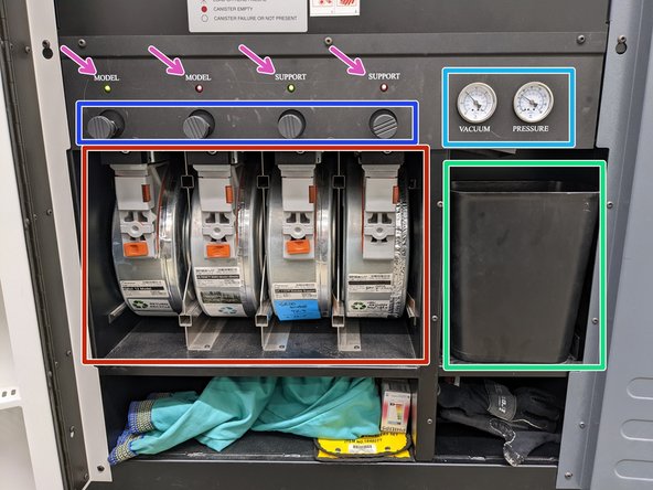
Canister Bays - The two LEFT bays are for MODEL material and the two RIGHT bays are for SUPPORT material
-
Purge Waste Bucket - Catches all purged materials during prints
-
Platen Vacuum and Filament Path Pressure gauges - Monitors the suction on the DISPOSABLE build plates as well as the available building air pressure
-
Drive Block Levers - The drive block levers allow for the filament canisters to be LOADED and UNLOADED
-
Canister LEDs - These lights will indicate the STATUS of each canister bay. It will either be OFF, SOLID GREEN, FLASHING GREEN, or RED
-
-
-
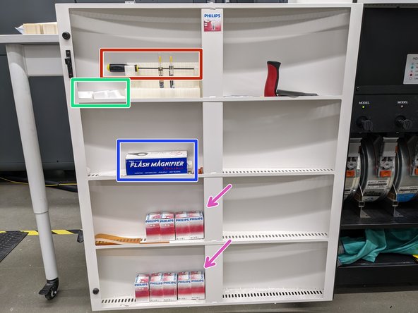
Screw Driver - This screwdriver is ESSENTIAL to have when OPERATING on the PRINT HEAD GANTRY
-
Purge Blocks - There are a VARIETY of PURGE BLOCKS for different materials because the INTERNAL TEMPERATURE of the OVEN will change depending on the material being printed and only certain blocks can withstand the temperatures
-
Flash Magnifier - Used when CALIBRATING the print head
-
Lightbulbs - Occasionally we will need to replace the lightbulbs in the oven so we can SEE the BUILD PLATE
-
-
-
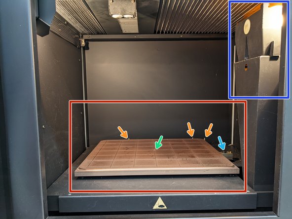
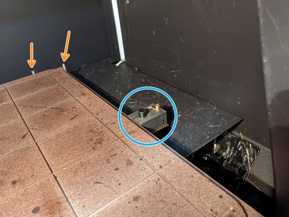
Platen - This is where the disposable BUILD plates are placed
-
Vacuum Port - This SUCTIONS the disposable build plates to the platen
-
Tip Sensor - Used to CALIBRATE the tips
-
Debris Chute Hood - Ensures PURGED MATERIAL does not FALL onto the BUILD plate
-
Barriers - Aids in ALIGNING the build plates on the platen
-
-
-
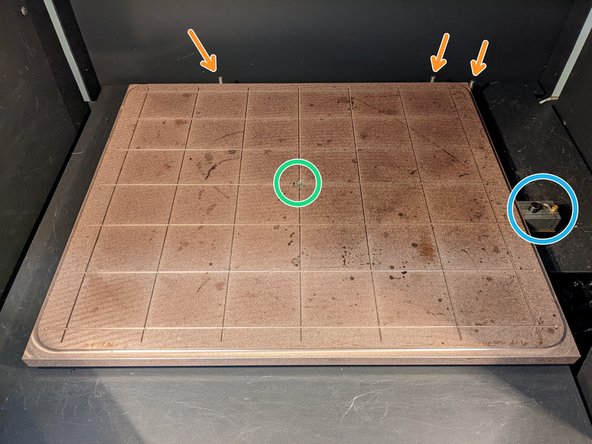
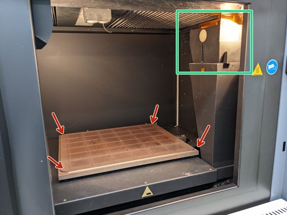
Platen - This is where the disposable BUILD plates are placed
-
Debris Chute Hood - Ensures PURGED MATERIAL does not FALL onto the BUILD plate
-
Lift straight UP and then move to the LEFT to remove the hood
-
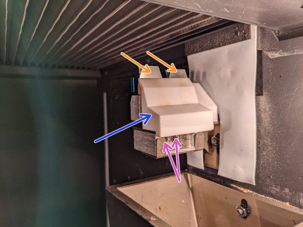
Purge Block - Assists in REMOVING any excess MATERIAL from the NOZZLES
-
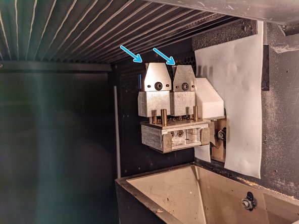
Flicker/Brush Assembly Adjustment Screws - Used to SECURELY mount the FLICKER BRUSH assembly
-
Flickers - Assists in REMOVING any excess MATERIAL from the NOZZLES
-
Brushes - Assists in REMOVING any excess MATERIAL from the NOZZLES
-
They are located BEHIND the FLICKERS
-
-
-
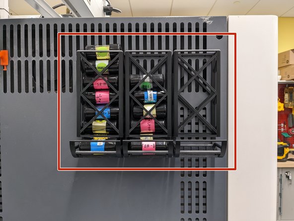
Fortus Tip Holders - The Fortus has the ability to print in a VARIETY of MATERIALS and can extrude this materials in a variety of SIZES which we STORE on the TOP LEFT SIDE PANEL
-
The Fortus CAN NOT CROSS CONTAMINATE materials which is why we have a large abundance of tips
-
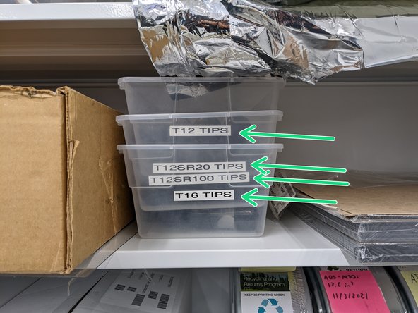
New Tips - We store brand NEW TIPS in small bins on the SECOND HIGHEST SHELF of the Fortus CABINET
-
-
-
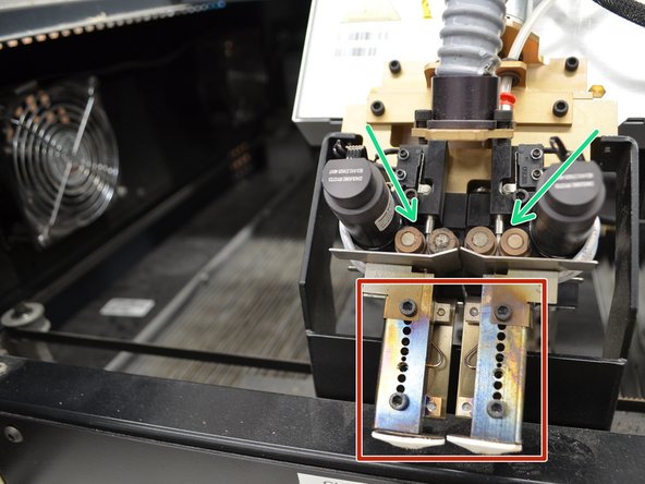
Liquefiers - There are TWO LIQUIFIERS that melt that plastic. One for model and support.
-
These reaches EXTREMELY HIGH temperatures so be careful when handling them
-
Filament Drive Gears - These FEED the filament into the LIQUIFIERS so that the filament can be extruded
-
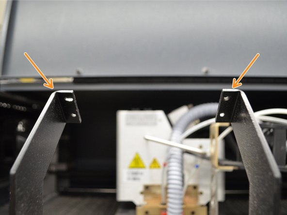
Head Maintenance Bracket - This is used when SWITCHING tips on the head assembly or performing MAINTENANCE
-
-
-
User Interface - ' ALL'' operations including maintenance, calibration, and running jobs are done through the interface
-
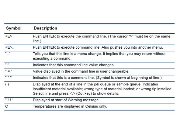
The next photo explains basic COMMANDS that the BUTTONS correlate to
-