Introduction
Whenever one or both tips are replaced, the offsets between them must be calibrated to ensure prints are accurate and successful. This guide details the necessary steps to determine the tip offsets in the X, Y, and Z directions and how to input those values to the machine.
-
-
There are two stages to calibration: first determine the X and Y offsets, then determine the Z offset. It is imperative that you calibrate X and Y before attempting to calibrate Z
-
Both stages are recursive; you may have to repeat the X and Y procedure several times before the results are good enough to move on the the Z procedure
-
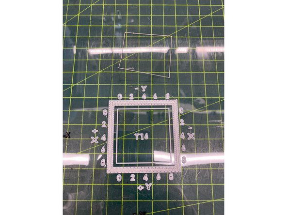
Stratasys recommends that each build sheet should be single-use. In the case of calibration, the number of calibration prints makes this impractical. Take care to avoid overlapping subsequent calibration prints
-
-
-
If you followed the material changeover guide, there should already be a calibration part ready. In that case, skip this step
-
Place a build sheet on the platen. See step 4 of this guide for details and troubleshooting about inserting a build sheet
-
Once the build sheet is secure, navigate to Operator Control > Calibrate > Calibration Job
-
Select Locate Part Start.. and use the 2, 4, 6, and 8 keys to jog the head to the desired start position. It is recommended that you place the first calibration part at the front left corner of the build sheet
-
When selecting a part start, the model tip indicates the front left corner of the bounding box of the part
-
Press Enter to set the part start, then select Continue.. to begin the build
-
-
-
Remove the build sheet with the completed calibration part, and place it on a flat surface
-
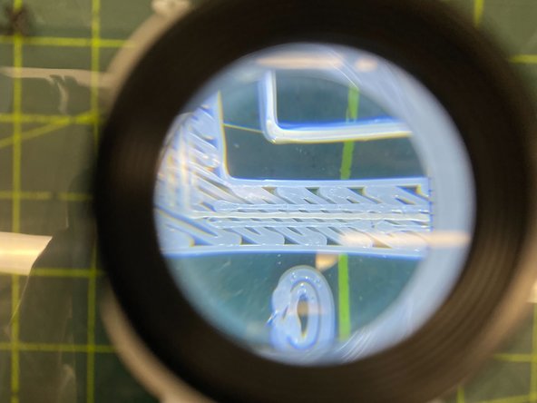
Use the illuminated magnifier stored in the canister bay door to inspect the outer box of the calibration part
-
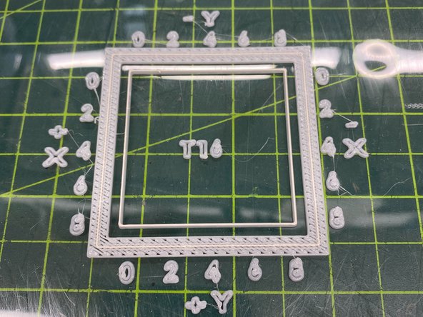
You will see three lines of material on each side of the box: two parallel lines of model material with a line of support material between them
-
Each side of the box corresponds to a specific axis: the top of the box is negative Y, the bottom is positive Y, the right is negative X, and the left is positive X. The part includes printed labels that illustrate this
-
Move along each side of the box to find the spot where the support line appears most centered between the parallel model lines. There should be a spot on one of the two Y sides and another on one of the two X sides
-
Take note of the closest printed number to each of the two locations you identify. Be sure to include the sign (positive/negative) as well
-
-
-
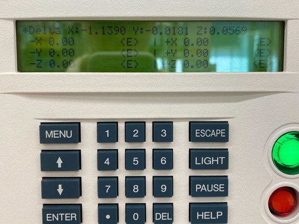
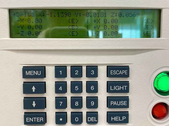
Navigate to Operator Control > Calibrate > Tip Offset Value
-
Input the values you recorded from inspecting the calibration part. For example, if you found that X was most centered at 4 on the right (negative) side, input 0.004 in the negative X field and press Enter
-
Repeat steps 2-4 until the line of support material on the calibration part is centered at (or very near) 0 on all four sides
-
-
-
Remember to only perform this step after X and Y are calibrated. You may use the final part from X and Y calibration to begin this process
-
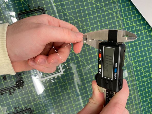
Use a razor blade or knife to carefully peel the top layer off the inner box of the calibration part. This top layer will be support material, while all the layers beneath it are model material
-
Measure the thickness of this layer using good digital calipers. Take several measurements on all four sides, avoiding the corners of the box and any bubbles or defects that may be present
-
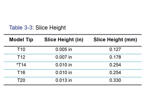
Take note of the average measurement and compare it to the slice height that corresponds with the tips that are currently installed
-
-
-
Navigate to Operator Control > Calibrate > Tip Offset Value
-
Input the difference between the value you recorded from inspecting the calibration part and the prescribed slice height. For example, if you are using a T16 model tip (0.010 in) and you measured 0.008 in, input 0.002 in the +Z field
-
Repeat steps 2, 5, and 6 until the measured thickness is within +/- 0.0005 inches of the tip slice height
-