-
-
The general process of creating a 3D design in most CAD software: first create a sketch, then manipulate that sketch into a 3D solid
-
The figure in the red box is a sketch. It's a collection of lines, curves, and closed shapes. To create a solid, the sketch must form a closed profile.
-
We can make the 3D shape in the orange box by applying the extrusion tool to the sketch.
-
The design timeline in the bottom left of the window shows which tools we used. As indicated there, this shape was made with a single sketch and extrusion.
-
This is just one example of the general process used to create solid bodies in CAD.
-
This guide gives an overview of some of the tools and techniques available when making a sketch. By no means is this list exhaustive. If you want to learn more advanced sketch tools, feel free to check out the module series for intermediate Fusion 360 users.
-
The guide on Introduction to Solid Features in Autodesk Fusion discusses some of the tools and techniques for turning a sketch into a solid body
-
-
-
To start a new sketch, click on the "New Sketch" icon
-
Sketches require a reference plane. Click on the plane on which you wish to create the sketch
-
-
-
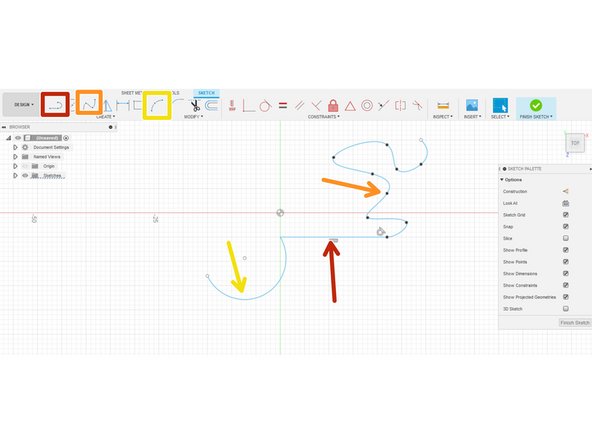
This figure shows a few of the most commonly used tools to create lines and curves in a sketch.
-
The line tool, shockingly, creates a line
-
The Spline tool creates a curve that interpolates several points.
-
The arc tool creates an arc defined by either three points, or two points and a radius of curvature.
-
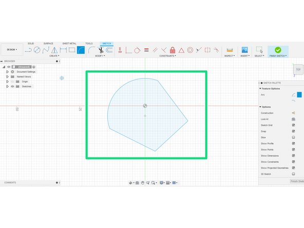
Connecting any line or curve can create a closed profile, denoted with a blue-shaded interior. This profile consists of three lines and an arc.
-
We encourage you to take a pause here and try out these tools in Fusion 360 before continuing
-
-
-
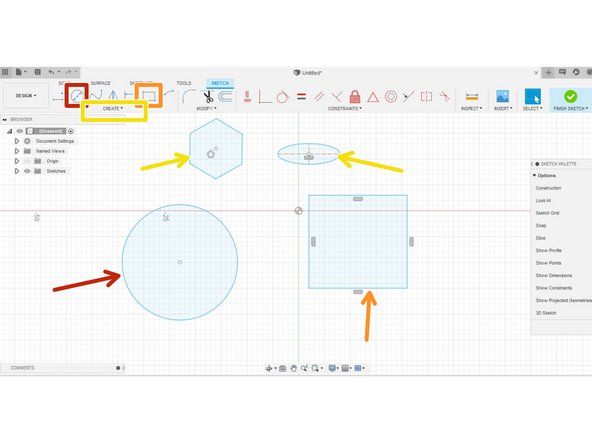
In addition to lines and curves, Fusion 360 has tools to make shapes in sketch mode. Note that all of the shapes are automatically closed profiles
-
Typically when making a shape, the user has the option of specifying important dimensions.
-
Multiple tools exist to make each shape by specifying different dimensions. For example, this circle was made by placing a center point and specifying the diameter.
-
The two point rectangle shown here is made by placing the points on opposite corners.
-
The polygon tool enables the creation of a regular polygon with a number of sides specified by the user either circumscribed or inscribed into a circle. This tool is located in the drop down menu.
-
The ellipse tool enables the user to make an ellipse by specifying the center point, major and minor axes. this tool is also typically located in the drop down menu.
-
-
-
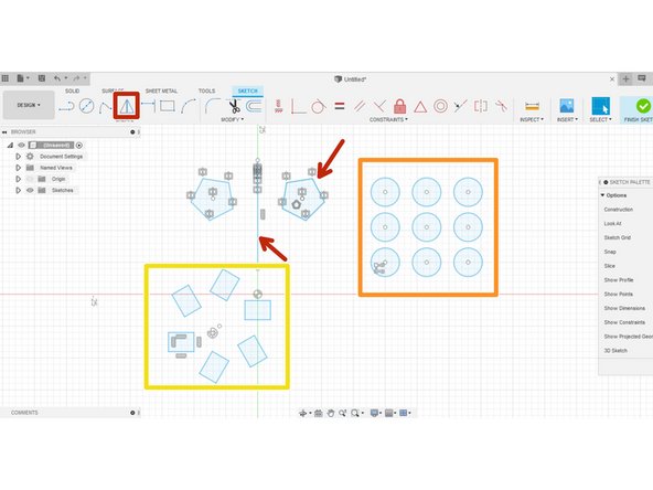
Pattern tools repeat the same sketch features (line, curve, or shape).
-
The mirror tool reflects a shape over a line. This command can mirror both closed profiles and lines or curves.
-
The rectangular tool makes a pattern of a sketch feature in a rectangular lattice. By default, the two axes of the rectangle align with axes of the sketch plane; however, the user can specify the axes as a line.
-
The circular pattern rotates a sketch feature around a point
-
-
-
This guide gives an introduction to a few of the most important and commonly used tool for making sketches in Fusion 360.
-
We encourage you to take some time after reading this guide to play with each of the tools at home. Try to recreate the cross section of objects a Fusion sketches.
-
To learn some of the basics for turning a sketch into a 3D model, refer to Introduction to Solid Features in Autodesk Fusion.
-
Cancel: I did not complete this guide.
One other person completed this guide.


