Introduction
This guide will serve as an introduction to the Keithley 2700 Multimeter/Data Acquisition/Switch Systems. It will show the user how to use the all the basic functions of the machine.
-
-
Power switch and special keys
-
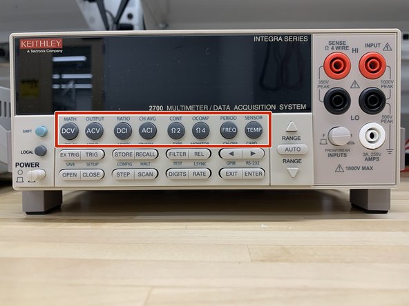
Function and operation key (top row)
-
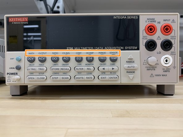
Function and operation key (middle & bottom row)
-
Range keys
-
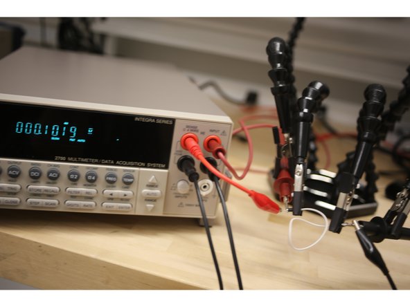
Display
-
Input selector
-
Probe inputs
-
-
-
Push the power switch to turn on the 2700.
-
SHIFT - Use to select a shifted function or operation.
-
LOCAL - Cancels GPIB remote mode.
-
-
-
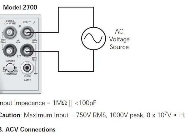
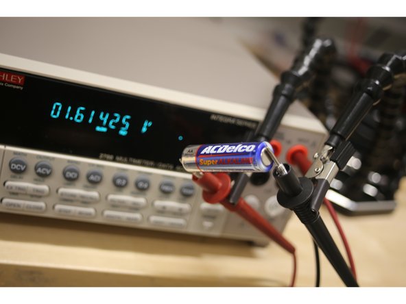
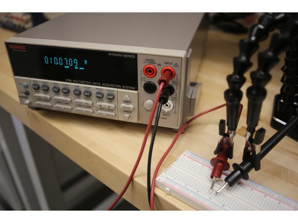
Connect the probes as shown.
-
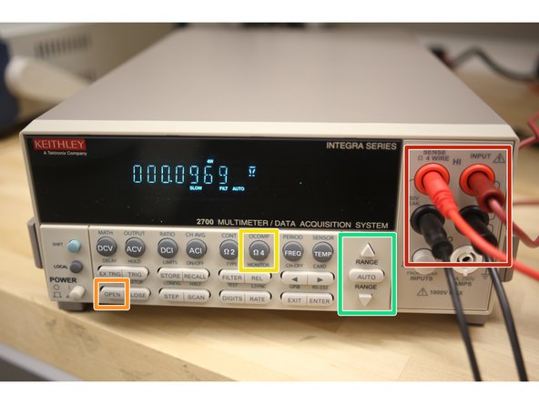
Make sure the INPUT switch is in the F position.
-
If the display shows a switching channel is closed, press OPEN to open it.
-
Select the DCV for DC voltage or ACV for AC voltage.
-
Use RANGE keys to select a range consistent with the expected voltage.
-
-
-
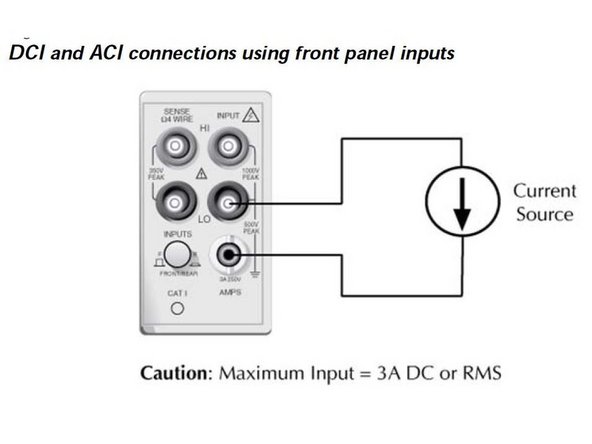
Connect the probes to the white and black inputs on the right.
-
Make sure the INPUT switch is in the F position.
-
If the display shows a switching channel is closed, press OPEN to open it.
-
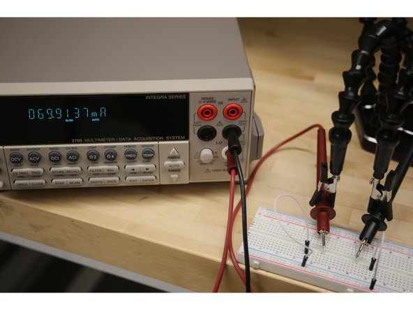
Select DCI for direct current or ACI for alternating current.
-
Use the RANGE keys to select a measurement range consistent with the expected current or use AUTO.
-
Insert the probes into the circuit such that current can flow through the machine and be measured.
-
-
-
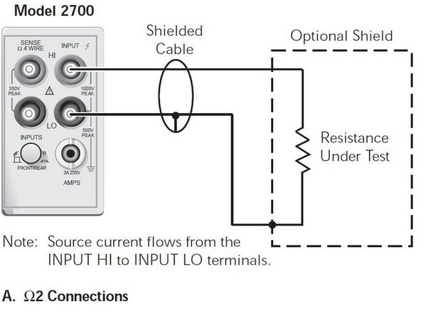
2 wire mode is typically for >1kΩ measurements.
-
Connect the probes to the red and black inputs on the right.
-
If the display shows a switching channel is closed, press OPEN to open it.
-
Select 2Ω for the 2 wire resistance function.
-
Use the RANGE keys to select a measurement range consistent with the expected resistance, or press AUTO for auto-ranging.
-
Resistance will be measured between the two probes.
-
-
-
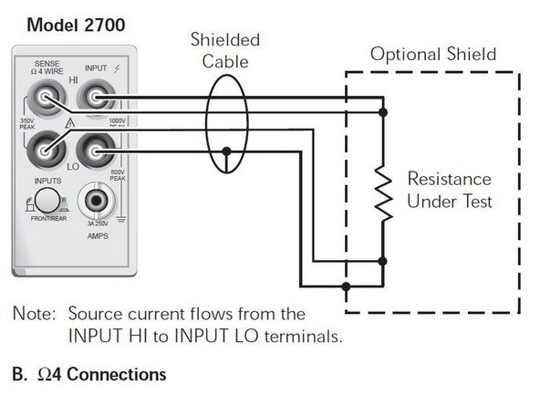
4 wire mode is typically for <=1kΩ measurements.
-
Traditional ohm meters (2Ω mode) usually apply a small current and measure the resulting voltage to calculate resistance. 4 wire mode utilizes a voltmeter in parallel with an ammeter to calculate resistance. This reduces the severity of the probes' internal resistance on measurement and is called a Kelvin connection.
-
Connect probes in all four red and black inputs.
-
If switching channel is presently closed (displayed), press OPEN to open it.
-
Select 2Ω.
-
Use the RANGE keys to select a measurement range consistent with the expected resistance, or press AUTO for auto-ranging.
-
Measure the device with both red leads on one side and both black leads on the other.
-
-
-
DCV - DC voltage measurement function.
-
ACV - AC voltage measurement function.
-
DCI - Direct current measurement function.
-
ACI - Alternating current measurement function.
-
Ω2/Ω4 - 2/4-wire resistance measurement function.
-
FREQ - Frequency measurement function.
-
TEMP - Temperature measurement function.
-
-
-
MATH - Configures and controls mX+b, percent, or reciprocal (1/X) calculation.
-
OUTPUT - Configures and controls digital and audio (beeper) output for limits.
-
RATIO - Enables/disables channel ratio.
-
CH-AVG - Enables/disables channel average.
-
CONT - Configures and controls continuity test.
-
OCOMP - Enables/disables offset compensated ohms with Ω4 function selected.
-
PERIOD - Selects period measurement function.
-
SENSOR - Configures temperature measurements.
-
-
-
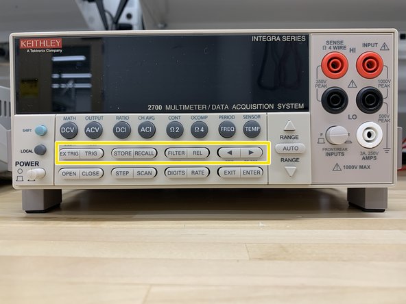
EX TRIG - Selects external triggering (front panel, bus, trigger link) as the trigger source.
-
TRIG - Triggers a measurement when in external triggering (EX TRIG).
-
STORE - Sets the number of readings to store and enables the buffer.
-
RECALL - Displays stored readings and buffer statistics. Use the arrow keys to navigate through buffer.
-
FILTER - Enables/disables filter for selected function.
-
REL - Enables/disables relative for selected function.
-
< and > - Dual function—Manually scans switching channels. When in a menu, these keys control cursor position for making selections or change values.
-
-
-
DELAY - Sets user delay between trigger and measurement.
-
HOLD - Holds reading when the selected number of samples is within the selected tolerance.
-
LIMITS - Sets upper and lower limits for readings.
-
ON/OFF - Enables/disables limits.
-
TYPE - Configures and enables filter for selected function.
-
MONITOR - Selects and enable/disables monitor channel.
-
CH-OFF - Disables channel for a scan (must be in scan channel setup mode).
-
CARD - Identifies switching modules installed in mainframe. Set up switching modules that require configuration. View closed channels and channel settings for switching modules that require configuration.
-
-
-
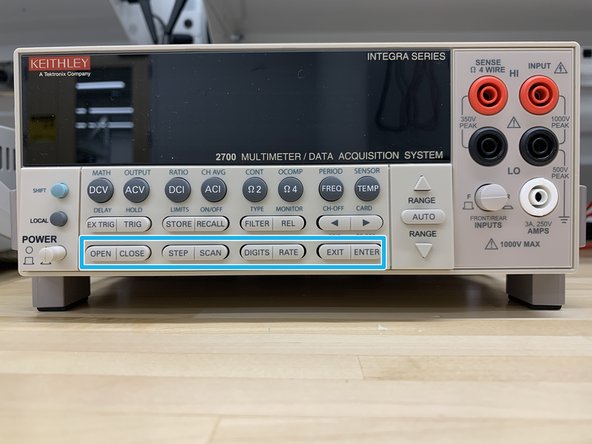
OPEN - Opens closed channel.
-
CLOSE - Closes specified channel.
-
STEP - Steps through channels; sends a trigger after each channel.
-
SCAN - Scans through channels; sends a trigger after last channel.
-
DIGITS - Sets display resolution for all functions.
-
RATE - Sets measurement speed (fast, medium, or slow) for all functions.
-
EXIT - Cancels selection, moves back to measurement display.
-
ENTER - Accepts selection, moves to next choice or back to measurement display.
-
-
-
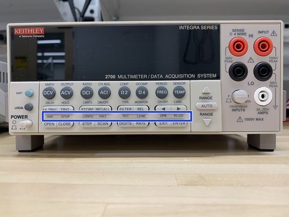
SAVE - Saves up to four instrument setups for future recall, and selects power-on setup.
-
SETUP - Restores a default setup (factory or *RST) or a saved setup. Enables/disables buffer auto clear, auto scan, and auto channel configuration. Sets timestamp, date, and time. Displays serial number of Model 2700.
-
CONFIG - Selects and configures a simple scan or an advanced scan.
-
HALT - Disables step/scan.
-
TEST - Selects the calibration menu, display test or the key-press test.
-
LSYNC - Enables/disables line cycle synchronization. When enabled, noise induced by the power line is reduced at the expense of speed.
-
GPIB - Enables/disables GPIB and selects address.
-
RS-232 - Enables/disables RS-232 interface; selects baud rate, flow control, and terminator.
-
-
-
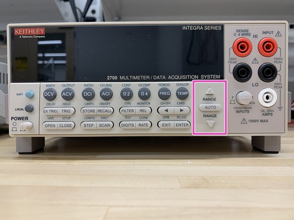
Δ and ∇ - Dual function. Selects the next higher/lower measurement range for the selected function. When in a menu, these keys make selections or change values.
-
AUTO - Enables/disables autorange for the selected function.
-
-
-
Front panel inputs (out position)
-
Switching module inputs (in position)
-
-
-
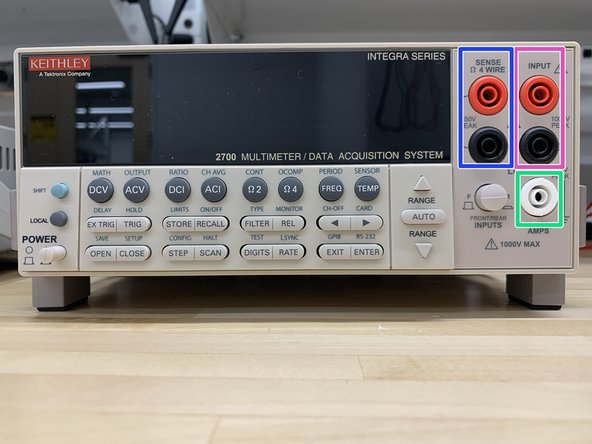
INPUT HI and LO - Used for DCV, ACV, Ω2, CONT, FREQ, PERIOD, and TEMP measurements.
-
SENSE HI and LO - Use with INPUT HI and LO for Ω4 and RTD TEMP measurements.
-
AMPS - Use with INPUT LO for DCI and ACI measurements.
-