
Introduction
Keyance is a very good scanner that capable of scanning part with very small feature. However, its biggest drawback is that it can only scan the object from the top. Therefore, the bottom and side sections cannot be captured in a single scan. Users can always rotate the object to scan all section of the part. However, Keyance Analysis software is not capable to align and combine all of the scan data. Therefore, Geomagic Design X software is used for combining the scan data.
This tutorial will teaches how to combine multiple scans taken from different angle into a single complete scan. The tutorial assume that the users have completed the beginning tutorial and have sufficient skill to operate the scanner.
-
-
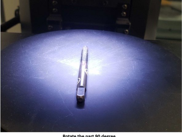
In this tutorial, you will scan a drill head as shown in the first figure using Keyance and combine the scan result into a single scan file
-
As the drill head is consist of multiple repeated patterns, several markers need to be added for assisting the alignment process
-
The marker is a sticker with a black dot on it as shown in the second figure.
-
Start by placing 2 or 3 stickers on the drill. It is recommended to place the sticker in multiple different locations as shown in the first figure to make the alignment easier
-
Turn on the scanner and the Viewer software
-
Place the drill on the scanner as shown in the third figure
-
-
-
Now you need to use the Stitching feature to scan the entire drill head (Please refer to the beginner manual about how to use the stitching feature)
-
You should get a scan result as shown in the second figure
-
Export the scan result by going to File > Export > Output 3D CAD Data (See the third figure)
-
Set the File format as STL files and set Model as Surface
-
-
-
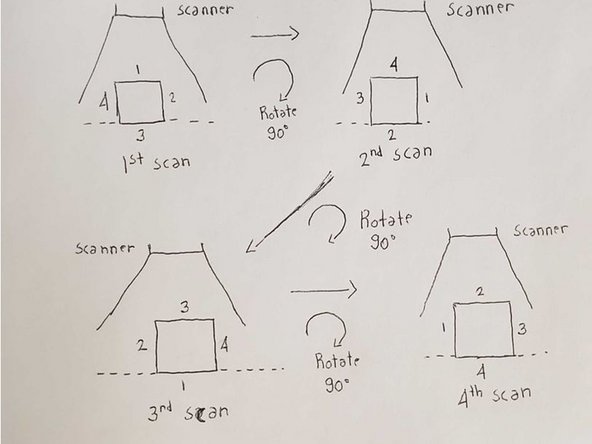
Rotate the part clockwise 90 degrees and repeat step 2
-
Repeat the scanning process wherein each process you rotate the part 90 degree until it returns to the original position
-
At the end of this stage, you should have 4 scans taken from 0 degrees, 90 degrees, 180 degrees, and 270 degrees (See the second figure for more detail)
-
-
-
Geomagic Design X software will be used for alignment and stitching of the scan results obtain from the Keyance
-
Geomagic Design X software is installed in the 3D scanning PC and laptop. You should be able to find it on the desktop. Let us know if you cannot find the software
-
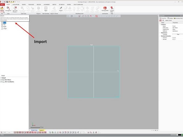
Import the STL files by using the Import feature under Home as shown in the first figure
-
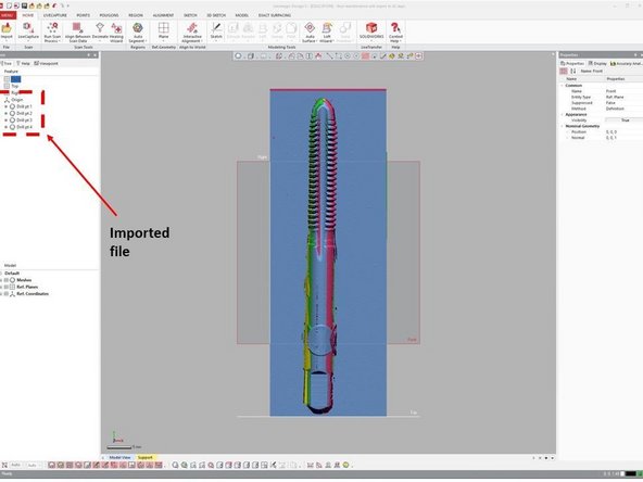
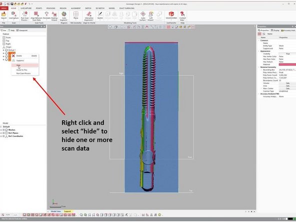
The imported scan data will be shown in the top left window as shown in the second figure
-
You can hide one or more scan data by right click (Using mouse) on the scan data and select Hide as shown in the third figure
-
-
-
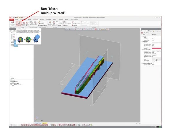
Now you need to perform data cleaning to remove any unwanted scan data (Such as the base plate)
-
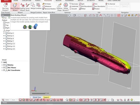
The data cleaning is part of the Mesh Buildup Wizard (Under Polygons) as shown in the first figure
-
Run the Mesh Buildup Wizard
-
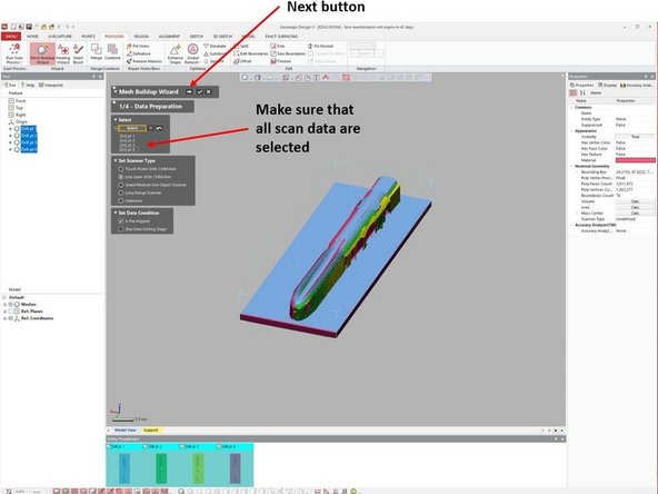
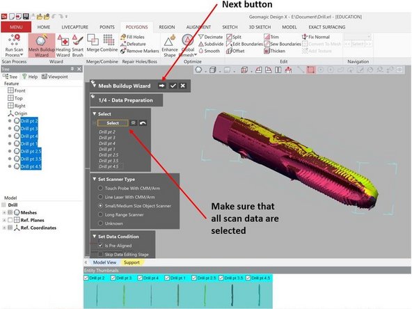
Under Data Preparation make sure that all scan data are selected as shown in the second figure
-
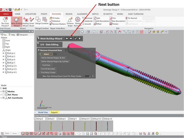
When finish, select the next button (Shown as the right arrow as shown in the second figure)
-
-
-
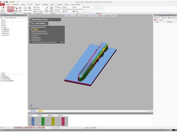
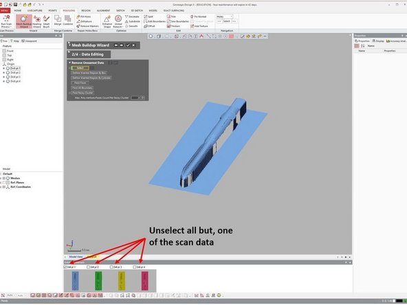
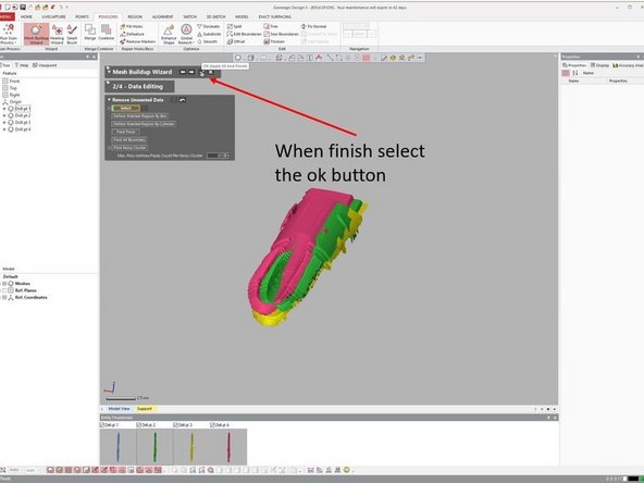
The second stage of the Mesh Buildup Wizard is Data Editing where you can remove unwanted scan data as shown in the first figure
-
For the data editing, it is recommended that you do it one scan at a time
-
This can be done by unselecting all but one of the scan data as shown in the second figure. This way you can do data editing on the selected scan data only
-
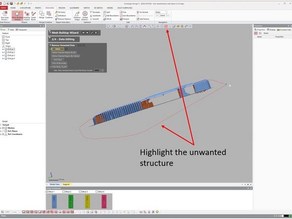
Highlight the unwanted structure (You can use rectangular, circular, or free form option from the top window) as shown in the third figure
-
-
-
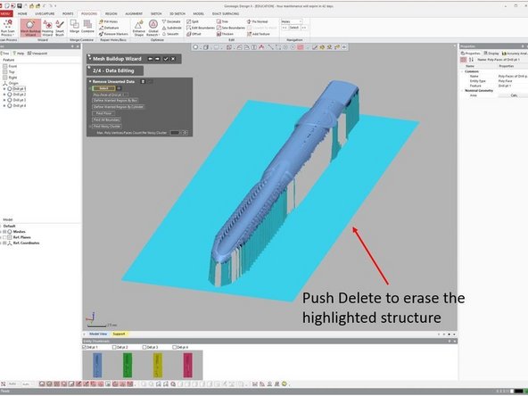
You can delete the highlighted structure by push the Delete button
-
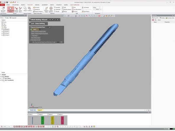
After deleting the unwanted structure, you should get a structure as shown in the second figure
-
Repeat the process for the second, third, and forth scan data
-
When finish select the Ok button from the top window as shown in the third figure
-
A window asking if you want to apply the remaining data merging stage will appear, select No
-
-
-
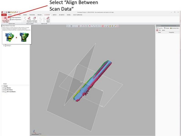
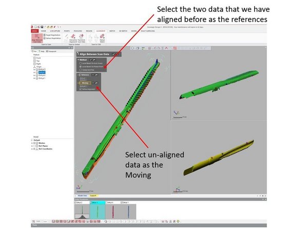
Multiple scan data can be aligned using Align Between Scan Data (See the first figure)
-
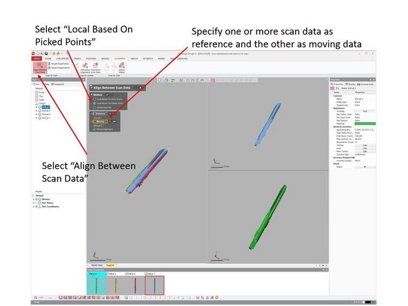
It is recommended to do the alignment using Local Based on Picked Point (See the second figure)
-
Specified one or more data as reference and another as moving data to be aligned
-
For the first alignment step, you may want to select the first scan data as the reference and the second scan data as the moving data
-
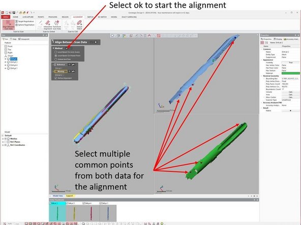
Select multiple common points from both data for the alignment (See the third figure)
-
The order of the points selected is important: 1st select the drill tip from the top figure, 2nd select the drill tip from the bottom figure, 3rd select the drill teeth from the top figure, 4th select the drill teeth from the bottom figure, and so on.
-
Select the check mark under Method to run the alignment
-
-
-
You should get an alignment result as shown in the first figure. Check it to make sure that they are aligned properly. Otherwise, repeat the process by adding more reference points
-
For the second alignment step, select the first and second scan data as the reference and the third scan data as the moving data as shown in the second figure
-
Repeat the alignment process until all of the scan data are well aligned with each other
-
When finish, select the ok button next to Align Between Scan Data top window to accept all of the alignment
-
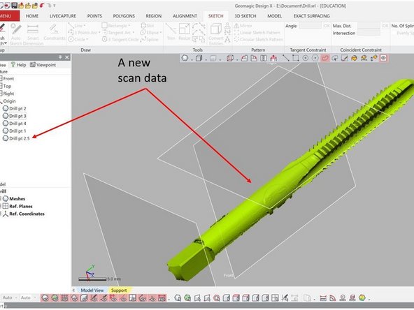
In case if you find that there is a scan data that is impossible to be aligned, you may want to run another scan which focuses on the interface region between the two scan data that you cannot align (The third figure)
-
You can then import this scan data and use it to help the alignment process
-
-
-
After finishing the part alignment sequence, you now should have a well align scan result as shown in the first figure
-
Now you need to merge all of those scan data into a single file
-
Rerun the Mesh Buildup Wizard under Menu to perform the data merging (See the first figure)
-
Under Data Preparation, make sure that all scan data are selected (See the second figure). Then select the next button
-
Under Data Editing, you can do any additional data cleaning if needed (Please refer to step 6 and 7 for instruction). Otherwise, you can hit the next button to go to the next step (See the third figure)
-
-
-
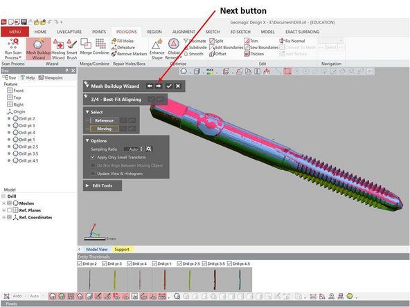
The third step is for Data Alignment. As you have done this before, you can just skip this step by hitting the next button (See the first figure)
-
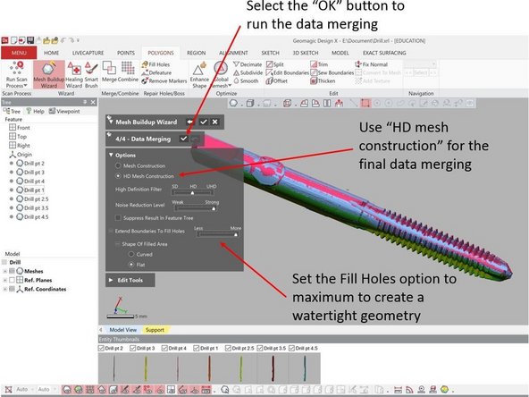
The last step is for Data Merging (See the second figure)
-
Use HD mesh construction for the data merging
-
Set the Fill Holes option to the maximum to create a watertight geometry
-
Select the OK button next to Data Merging to run the data merging
-
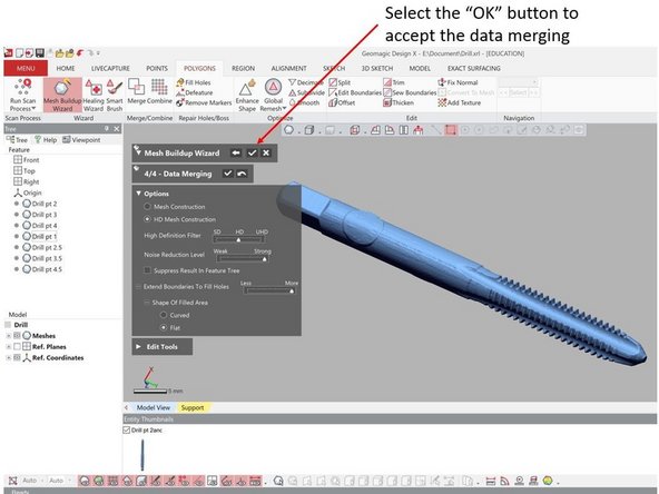
If the merged geometry is not in good quality, hit the Undo button which is next to the ok button. It is recommended to play around with the High Definition Filter and Noise Reduction Level to find their optimum values
-
When finished, select the “OK” button next to Mesh Buildup Wizard to accept the data merging (See the third figure)
-
-
-
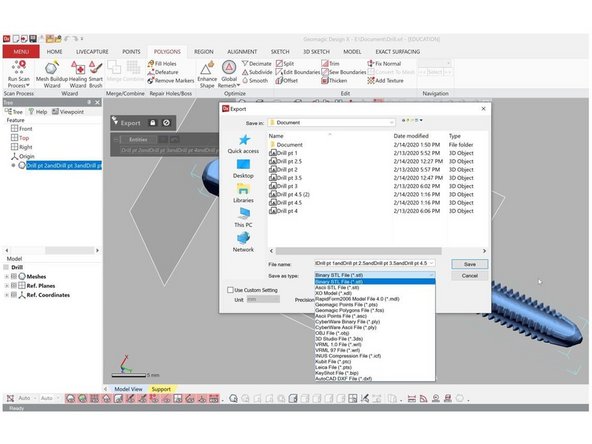
To export the file, go to Menu > Export
-
Select the mesh you want to export
-
Select the type of output file such as stl, asc, obj, etc.
-


Congratulation you have learn the advance skill needed to operate Keyence VR-3200 3D scanner
Congratulation you have learn the advance skill needed to operate Keyence VR-3200 3D scanner
Cancel: I did not complete this guide.
4 other people completed this guide.