
-
-
After scanning, the analyzer will open. For this guide, close the analyzer window and go back to the viewer.
-
If the scan was stitched, this menu will not appear.
-
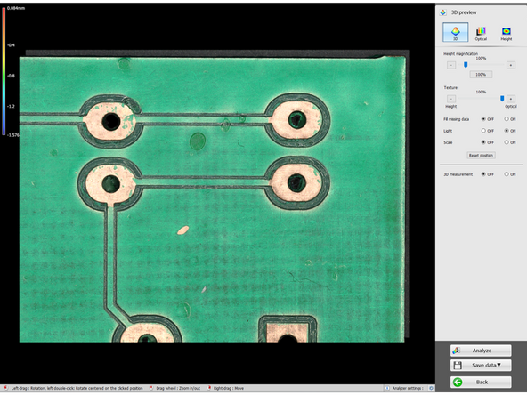
The following options are only available in the "3D" view
-
There are three views available- 3d, optical, and height heatmap views. These views are different representation of the data.
-
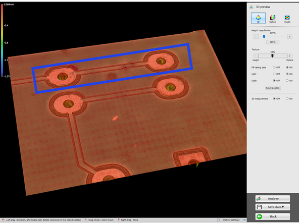
"Height Magnification" does not change the data captured, but will amplify height differences to be more visible to the naked ey.
-
"Texture" can change the appearance of the 3d model to be a mix between the optical texture and the height data.
-
There are a handful of switches here - "Fill Missing Data" will interpolate gaps in the height data, "Light" will change the brightness of the pixels to account for a light source in the room, and "Scale" will turn on a grid.
-
"Fill missing data" is not recommended for metrology purposes, as it will not be accurate
-
-
-
You don't have to run the scan to perform part measurment
-
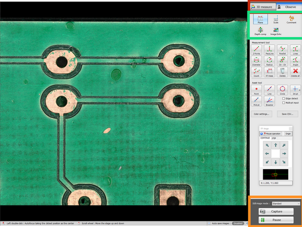
Switch to the Observe tab-from there, measurements can be made on a still image for basic metrology.
-
Select Observe to start the part measurement- note that any of the following configurations will NOT be saved for later modification.
-
If performing measurements in this mode, it is best to "pause" the observation to prevent any movement of the sample while defining measurements.
-
The top selections will change the menu below, and the options available
-
Pausing the view will remove the option to have depth comp and image enhancements if they were not applied before
-
-
-
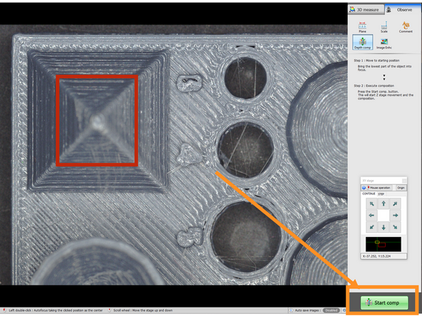
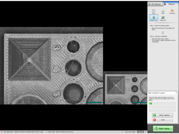
In order to take better plane measurements with a large height object (or to simply take better pictures), depth compensation can be utilized.
-
When focused on the main plane of this part, the tops of some of the features are not in focus. We can use depth compensation to make these parts clearer.
-
Press "start comp" and follow the instructions on the screen (this process is very easy)
-
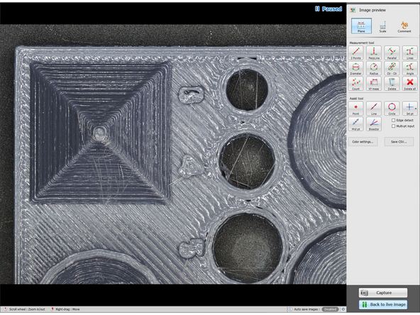
After the process completes, the menu will changed to the paused menu that allows plane measurements.
-
-
-
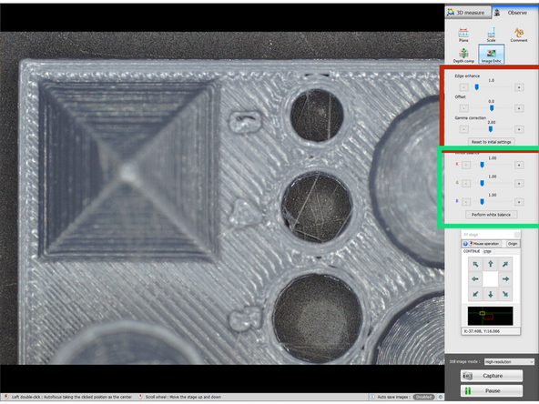
This tab is all visual adjustments- this will not affect data taken. As such, default settings are just fine for most scenarios
-
The top settings change various image values that may allow for better visual clarity
-
Edge Enhance - sharpness, this is not a substitute for proper focusing but can highlight contours
-
Offset - brightness offset, this can be used to raise or lower overall brightness.
-
Gamma correction - changes the gamma value of the image, which is slightly different from the brightness offset.
-
Individual RGB values can also be biased to potentially better represent colors.
-
"Perform white balance" is an automatic process that can better balance the colors of the image, but this does not make them truer to reality.
-
-
-
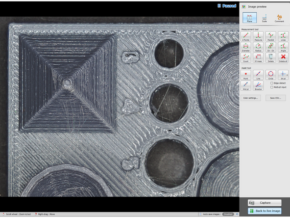
This page is divided into two main groups - Measurement Tools, and Assists tools. Assist tools SHOULD always be used before measurement tools, but are not strictly necessary.
-
All measurements and markers defined here will appear in any image that is saved, but will not be saved later for modification or verification- use the Analyzer for that.
-
The assist tools have two broad categories- feature definition and derived features.
-
"point", "line", and "circle" tools are all shapes that can be defined to assist with measurement.
-
"intersection point (int pt)", "mid point (mid pt)", and "bisector" all create new features derived from the previous ones.
-
Almost all of the options under "measurement tools" will measure linear distance between some features, except for the "angle" feature
-
If no assist feature is selected when making the measurement, the program will prompt the creation of these features in accordance with the settings selected in "assist tool"
-
"edge detect" will use the program's built in optical edge detection algorithms, and "multi pt input" will allow the user to define multiple points for the assist tools, where it will then interpolate and define a new feature.
-
-
-
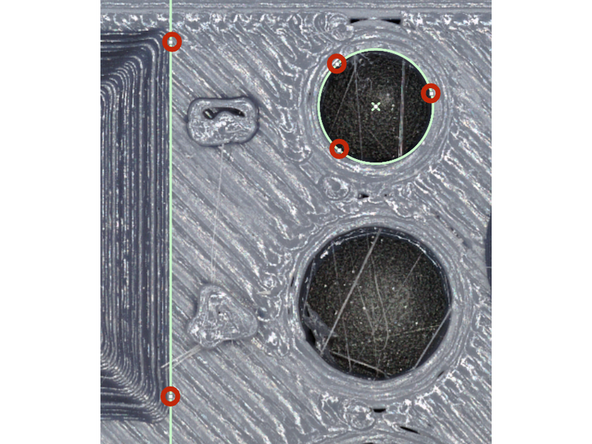
When creating an assist tool, try to line it up with a corresponding real feature on the part. (circles to circles, lines to edges, points to singular points)
-
If neither "edge detect" or "multi-pt input" is selected, when any of the assist tools are selected, it will prompt for the minimum number of points. (1 for pt, 2 for a line, 3 for a circle).
-
This mode is generally not recommended, as it is very prone to human error
-
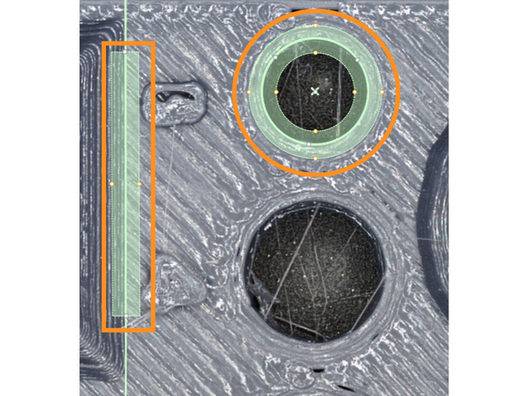
"edge detect" will let the user define a search area, and the program will find the best fitting line within that range.
-
Defining the search area centerline to match the shape of the feature but be slightly offset often gives the best definition of the edge.
-
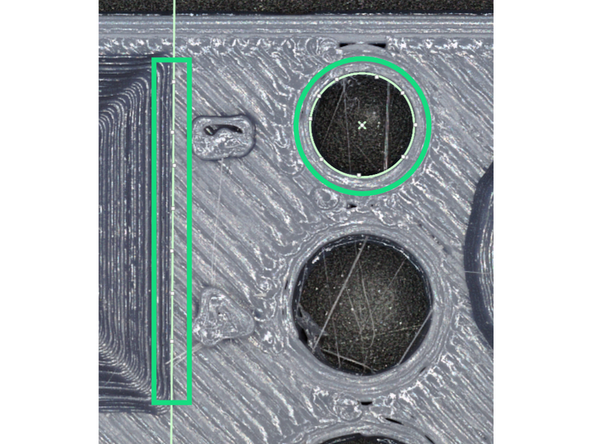
"multi-pt" input will allow the user to define multiple points, where it will then interpolate the feature from the points.
-
While this is better than the minimum number of points on the red bullet, it is still generally prone to human error. This mode should be used if edge detection fails repeatedly.
-
-
-
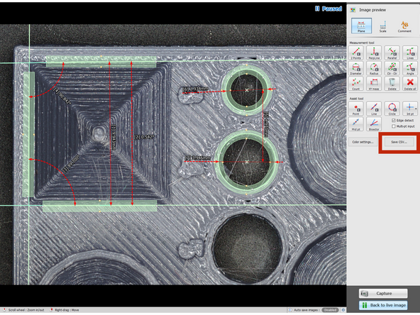
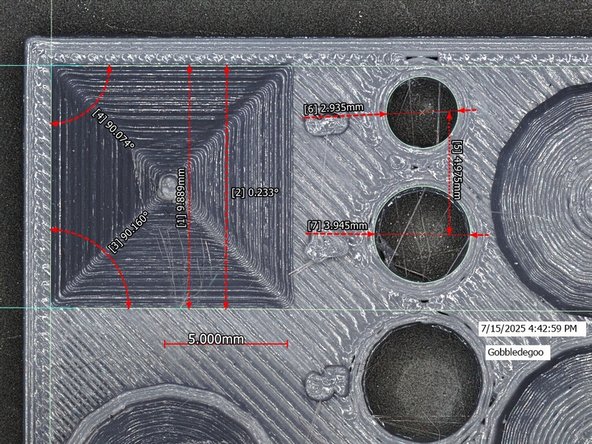
All of the measurement tools are fairly self explanatory, so this step will focus on how they might not be intuitive (the images are not very helpful)
-
"Parallel" creates a unique assist tool after the first line is selected (or defined). This tool will search for a parallel line within the search range, and thus is generally not recommended (since many lines are not parallel)
-
"Lines" is the better substitute, which will use the centers of the search areas of the lines defined, and does not require lines to be parallel.
-
"Lines", in conjunction with "Angle" often gives a truer impression of the lines.
-
All circle tools require selecting the edge of a circle feature, not the center.
-
After all measurements are defined, they can be saved in a .csv file
-
-
-
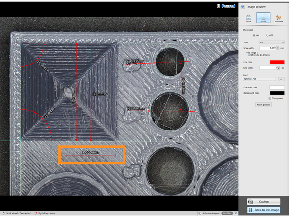
This tool simply defines a line of a set width.
-
The menu options allow changing of the appearance of the scale.
-
The text and scale line can be moved independently.
-
-
-
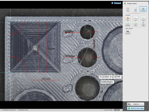
This tool allows creation of text, various shapes, and a date-time mark.
-
The final image export will have all measurements and marks, and come out as a .jpg file
-
Cancel: I did not complete this guide.
8 other people completed this guide.
