-
-
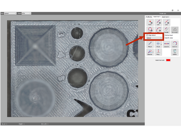
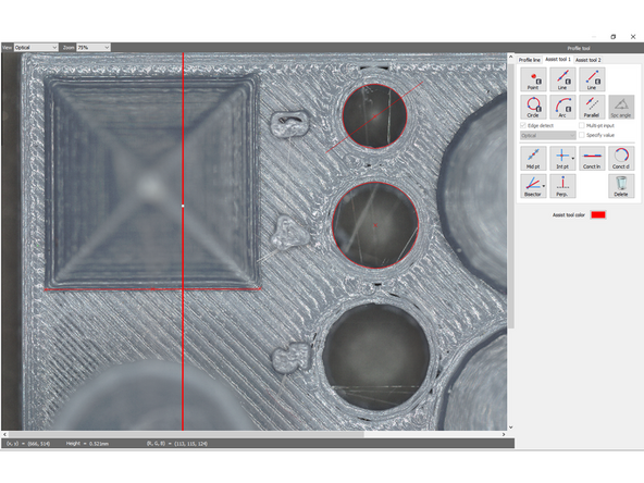
Assist elements do not create any measurements, instead, they can be used as a reference point or reference line when you set a measurement interval. Placing assist elements at measurement points, enables you to set measurement intervals more accurately and efficiently
-
Edge detect: When this is selected, an edge is extracted automatically from around the place you clicked.
-
Choose how to extract the edges from the pull-down list. Depending on the feature, Optical or Height may be more useful. The view can be swapped between the 2 to determine the best for each feature.
-
-
-
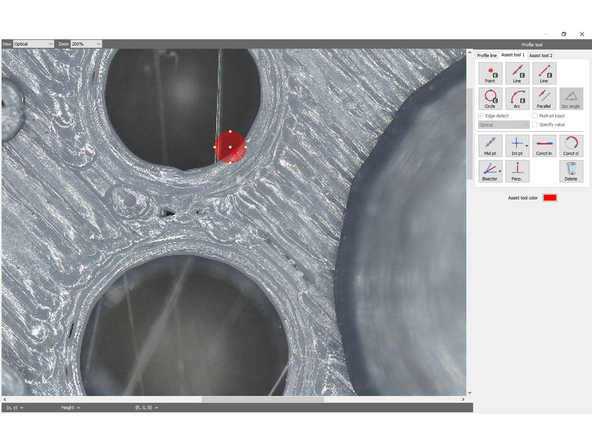
An element that expresses a point.
-
The point tool will create a point at an arbitrarily selected point.
-
When Edge detect is on, a circular area will be displayed when the point is created. This region can be rescaled and moved, and the best edge within your region will be selected for the point creation.
-
-
-
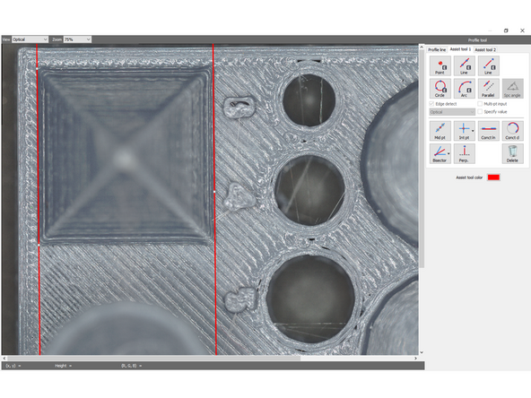
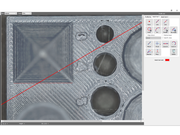
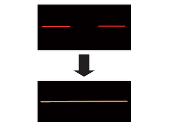
A straight line element that passes through two points (or more when [Multi-pt input] is selected).
-
Click one point and another to create a line through the two points. Existing point elements can be reused as selections.
-
The first line assist tool will create an infinite line across the selected points. This may throw off measurements when referencing it later to measure small areas since the overall average of the line is used.
-
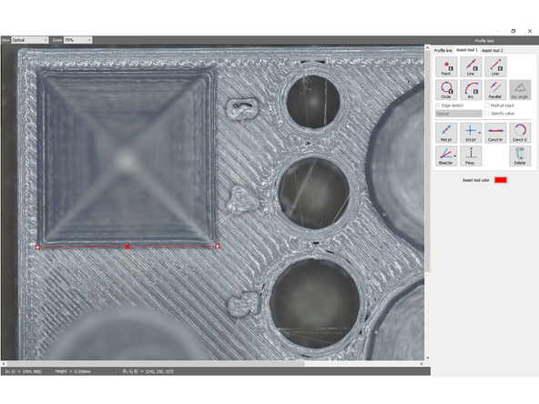
The second line assist tool will create a capped line between points which will be more accurate when measuring specific features.
-
Edge select will again create a region in which the line will search for the best edge.
-
-
-
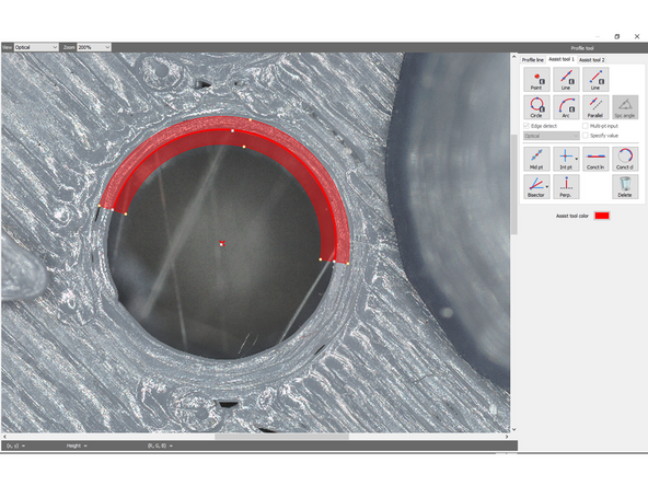
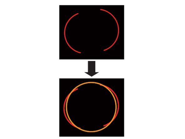
A circle element that specifies three points (or more when [Multi-pt input] is selected) on the circumference.
-
Selecting 3 points along the circumference of the circle will create the circle element. After the second point is selected a preview of the circle with the third point will be visible. Existing points may be re-used along the circumference.
-
Edge detect will create a region which the circle will auto snap to.
-
-
-
Generates an arc which is formed by three arbitrary points as the circle element.
-
The first and second points will generate a preview of the arc with the third being the end point of the arc. A center point is also added.
-
-
-
Generates a line which is parallel to the line which passes through two points as line element.
-
Either two points can be selected to make an initial line and then a third can be selected as the point for the parallel line to pass through, or initially an existing line can be selected to be parallel to.
-
-
-
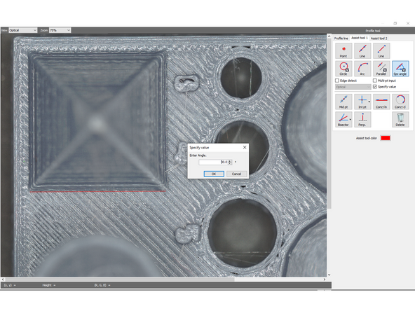
Generates a line which is intersecting the line that passes through two points at a specified angle as line element
-
In order to use this tool, specify value must be selected
-
A dialog box to specify the angle offset will pop-up when the tool is selected, and the angle is first input.
-
Then, a line is either created by the user by selecting 2 points or a pre-existing line is selected to offset the line from and a third point is selected to place the assist tool line.
-
-
-
Creates a middle point of two points as a point element.
-
Click the 1st point, and then move the mouse pointer. When you move the mouse pointer, the line segment and the middle point appear. Then select the second point. Pre-existing points can be re-used
-
-
-
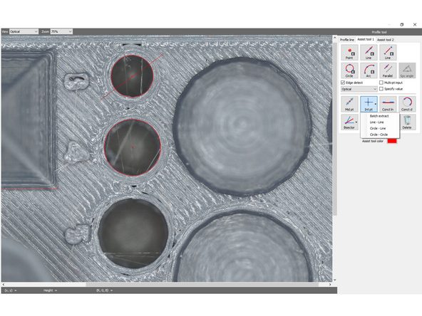
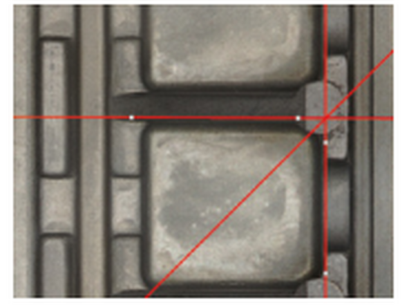
Creates the intersection of two lines, a line and a circle, or two circles as a point element.
-
Selecting the tool presents you with several options:
-
Batch Extract: The tool will search for all line-line, circle-line, and circle-circle intersections and add a point at each of them.
-
Line-Line: Specify a line and a second line and their intersections will have points added.
-
Circle-Line: Specify a circle and a line and their intersections will have points added.
-
Circle-Circle: Specify a circle and a second circle and their intersections will have points added.
-
-
-
Generates a line that connects multiple lines as line element.
-
Reusable element at the time of placement: Point, Line, Segment
-
1. Select an existing line element or point element.
-
2. Repeat up to 10 times.
-
3. When you have finished selecting, double-click any point or select [Confirm] from the right-click menu. A new line element is placed based on the selected point elements and the sets of points that created the line elements.
-
-
-
Generates a circle that connects multiple circles as circle element.
-
Reusable element at the time of placement: Point, Circle
-
1. Select an existing circle element or point element.
-
2. Repeat. Up to 10 elements can be selected
-
3. When you have finished selecting, double-click any point or select [Confirm] from the right-click menu. A new circle element is placed based on the selected point elements and the sets of points that created the circle elements.
-
-
-
Generates the bisector of two lines, a line and a point, or two points as line element.
-
Reusable element at the time of placement Point, Line, Segment
-
There are several options. Select the one required for your specific application, then select two points/lines depending on your selection.
-
After selecting [Line-Line] in measurement type, if the specified two lines are intersecting, Click the interior angle (or exterior angle) intersected by the two specified lines. The bisector in the angle intersected by the two specified lines is placed.
-
-
-
Generates a line which is perpendicular to the line passes through two points as line element.
-
Reusable element at the time of placement: Point, Line, Segment
-
Create a new line with 2 arbitrary points or select a pre-existing line. Then, a perpendicular line will be displayed. Selecting a 3rd point places the assist tool element.
-
-
-
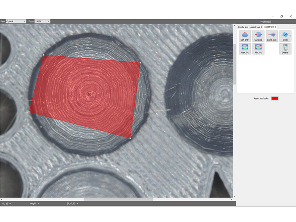
The stereoscopic shape in the specified tetragon being considered as a sphere, create a point element of the point at which the perpendicular line to the reference plane from the center point of the sphere and the reference plane intersect with each other. (huh?)
-
Select 4 points along the sphere/dome that you're trying to create a center point of. The area will highlight as more points are selected, and after 4 are selected, the midpoint will be shown.
-
-
-
The stereoscopic shape in the specified tetragon being considered as a side surface of a cylinder, create a straight line element of the line whose center axis is projected to the reference plane
-
Do not specify an area that spreads out of the cylinder (or the stereoscopic shape). (as well as sphere and cone) If the area spreads out of the cylinder, the software approximates the part that includes planes around as a cylinder. In this case, an accurate axis cannot be calculated.
-
The process is the same, select 4 points within the region of the cylinder and the axis will be added.
-
-
-
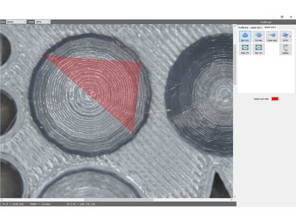
The stereoscopic shape in the specified tetragon being considered as a side surface of a cone, create a straight line element of the line whose center axis is projected to the reference plane.
-
The steps after this are the same as those for [Sph cntr]. When the tetragon is confirmed, the straight line of the center axis of the cone is placed.
-
-
-
Specifies a cross line of the planes estimated from the stereoscopic shape in the specified area
-
There are 2 options in the drop-down:
-
Reference surface - Free surface: Creates an intersection line between the reference surface and a surface specified arbitrarily. Selecting 4 points to define a region will create the intersection line with the surface originally defined as reference during measurement.
-
Free surface - Free surface: The user specifies two regions with 4 points which are then both used to find the intersecting line between them.
-
-
-
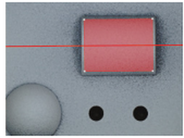
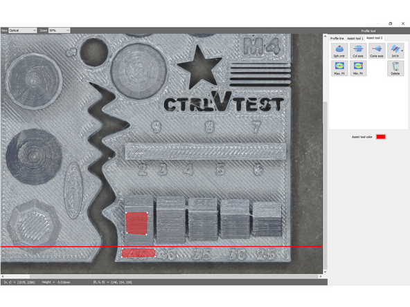
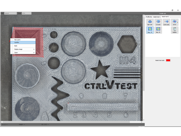
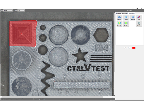
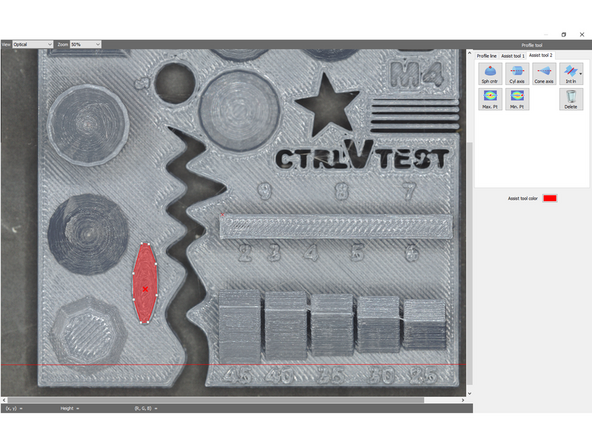
Generates the maximum point as a point element in the height direction within the specified area.
-
Select a region by specifying points, then right click and select confirm to define the region. The point with the highest height will be created.
-
-
-
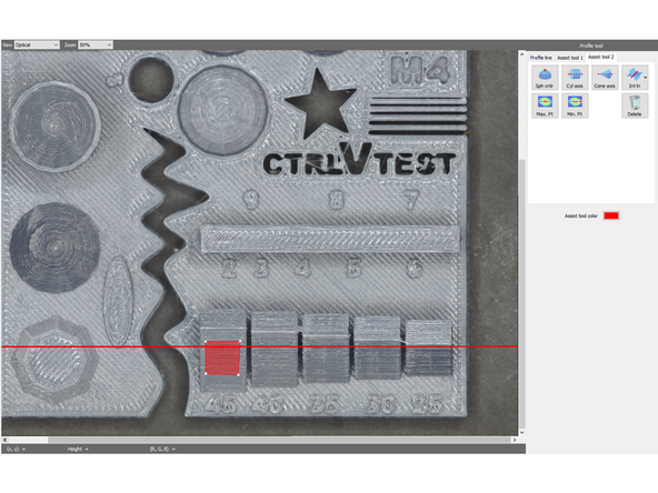
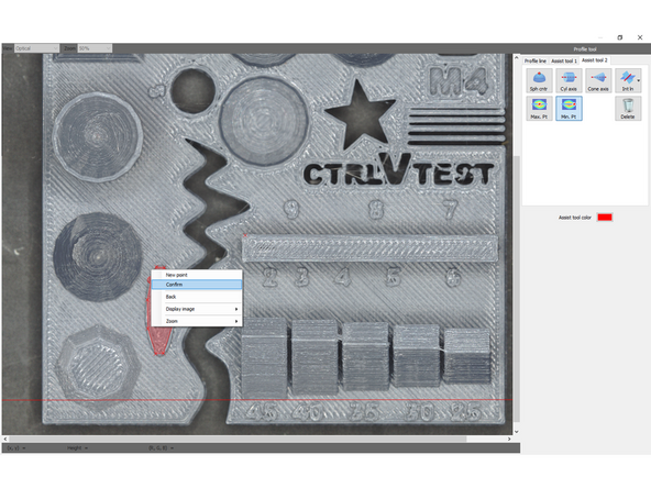
Generates the minimum point as point element in the height direction within the specified area.
-
Select a region by specifying points, then right click and select confirm to define the region. The point with the lowest height will be created.
-
![A straight line element that passes through two points (or more when [Multi-pt input] is selected).](https://d3t0tbmlie281e.cloudfront.net/igi/umd/ld4rPBRMALGZqnMr.medium)
![A circle element that specifies three points (or more when [Multi-pt input] is selected) on the circumference.](https://d3t0tbmlie281e.cloudfront.net/igi/umd/M35rPBRM33ChA1wj.medium)
Cancel: I did not complete this guide.
One other person completed this guide.