
-
-
This guide follows the process of scanning and post-processing this object: a sculpture of a sloth
-
Note: the pink sloth is the target object to scan. We cannot scan the bottom since removing the sculpture from its mount (black 3D printed rectangle) would damage it.
-
-
-
We are starting this guide assuming you have already learned the basics of operating the Romer Absolute Arm (Romer Absolut Arms Tutorial (Beginner)). Thus we are starting having already scanned what we can.
-
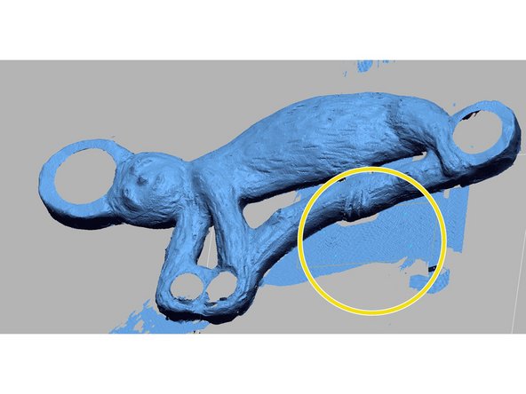
When we scanned the sloth, we captured some of the 3D printed base and some of the table. Since we will be using the base for our reconstruction steps later, keep that feature
-
Delete the scan of the table and other scanning artifacts
-
-
-
Now that we cleaned up our scan, we are going to create a reference plane on which we model the unseen face.
-
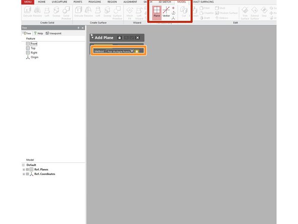
In the "Model" tab, select the "Plane" tool
-
Use the "Pick Multiple Points" option to create the reference plane
-
Place at least four points on the scan of the base preserved in the previous step
-
-
-
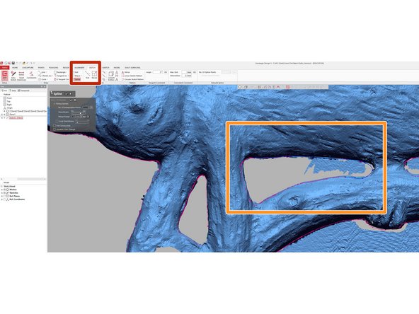
Now that we created a reference plane, we will use that to create a mesh sketch. This tool lets us create a sketch with geometry extracted from existing scans
-
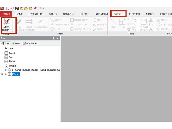
In the "Sketch" window, select "Mesh Sketch"
-
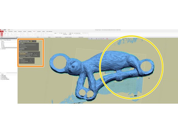
Make sure that the reference plane selected in the Mesh Sketch toolbar is the plane we created in step 3
-
Note that the new mesh sketch has extracted the contours of the scan. We will use these contours to trace out the boundaries of the face we could not scan
-
-
-
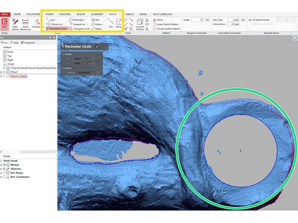
In this step, we will use the newly created mesh sketch to draw out the contours of the unseen face. The mesh sketch has extracted contours from the scan, but there are still gaps we manually fill
-
To create contours not easily modeled by basic geometries (e.g. circles or squares) open the "SP Line" tool in the "Sketch" tab
-
With the SP line, use the extracted contours as a guide and draw an SP line around each closed path. Do not trust that the mesh sketch automatically extracted closed loops; use extracted geometry as a guide and trace each path yourself
-
For contours that match basic shapes, use the appropriate sketch tool in the "Sketch" tab.
-
In this example we modeled the hole with a circle
-
-
-
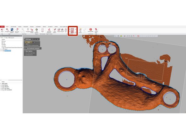
By this point, we have drawn out each closed loop or path in the mesh sketch. Now we are going to fill that face to create a surface.
-
In either the "Home" or "Model" tab, select the "Fill Face" command
-
Select the outer contour of the mesh sketch. This will fill the entirety of the unseen face.
-
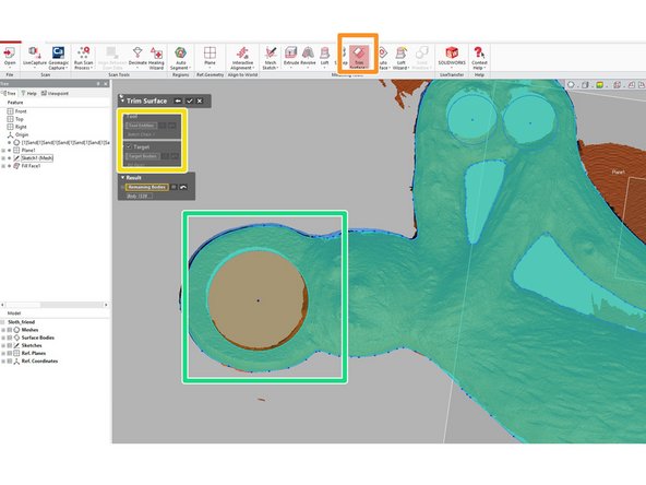
In the "Model" tab, select "Trim Surfaces"
-
Choose the filled face as the target body and a contour of a hole as the tool body
-
This will remove the region of the filled face where the original model had a hole. Repeat this step for all holes in the filled face
-
-
-
We have by this step finished modeling the unscanned surface. Now we will create some other features the scan could not capture, namely the inside surfaces of each hole
-
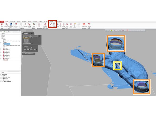
In either the "Home" or "Model" tab, select the "Extrude" command and insure it is set to surface extrude
-
Select the sketch contour of each hole with an unscanned inner surface. We will create a new surface for each of these sketch contours
-
Make sure to set the extrusion distance such that the new surface does not significantly intersect the existing scan
-
-
-
In this step we convert the modeled surface to a mesh feature and create a solid mesh from the two feature (scans and modeled surfaces).
-
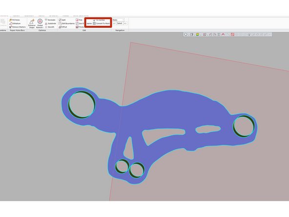
Select the modeled surface and use the "Convert to Mesh" tool in the "Polygon" window
-
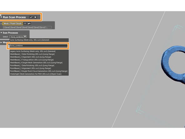
There is a standard command that combines mesh features. However, for reasons beyond my comprehension, this command does not work for converted mesh features. We found a work-around, described below:
-
Under "Run Scan Processes" select the the modeled surfaces and the scan, then select "force_combine". This will combine the surface and scan into a single mesh
-
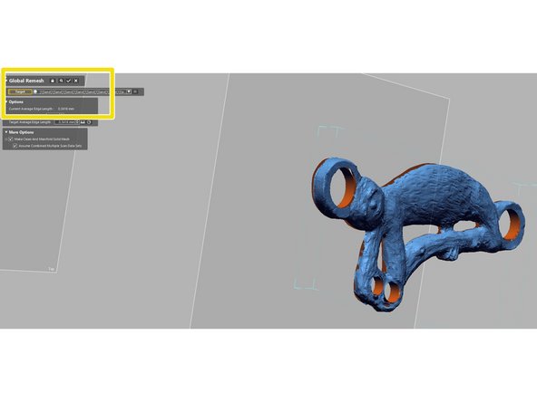
To create a solid and manifold mesh, run "Global Remesh" under the "Polygons" tab.
-


Cancel: I did not complete this guide.
2 other people completed this guide.