Tools
Parts
No parts specified.
-
-
All of the labelled Mold parts can be seen here
-
-
-
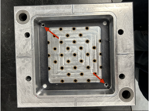
Insert the Injection Side Mold Insert into the corresponding mudplate.
-
Fix it to the mudplate using the 2 corner threaded holes with M6-22 bolts
-
-
-
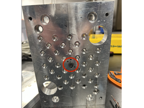
Insert the Center (Shorter) pin into the pin plate.
-
Insert the outer ejection pins into their corresponding holes.
-
The ejection pins do not need to be perfectly flush at this stage as long as the heads are seated inside their respective holes.
-
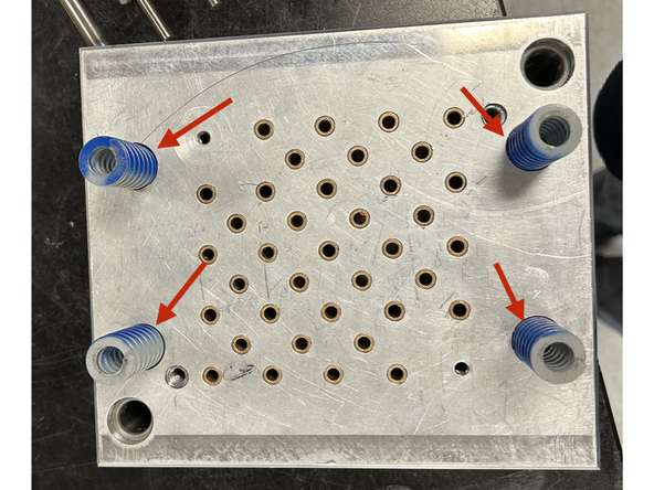
Insert the spring guide pins into the 4 corners.
-
-
-
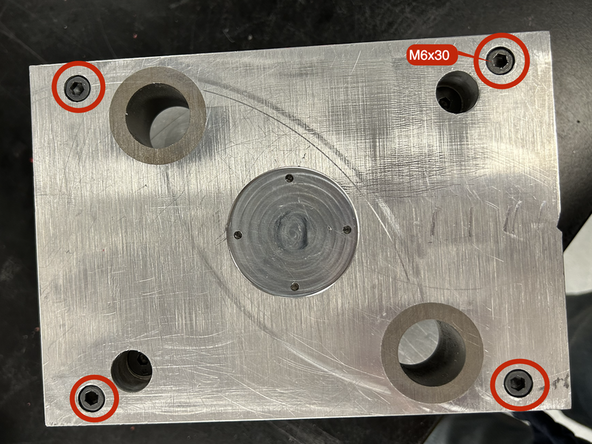
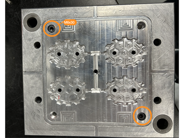
Afix the back pin plate to the front plate using 4 M6-30 bolts
-
Ensure you tighten the bolts evenly to prevent misalignment and damage to the threads.
-
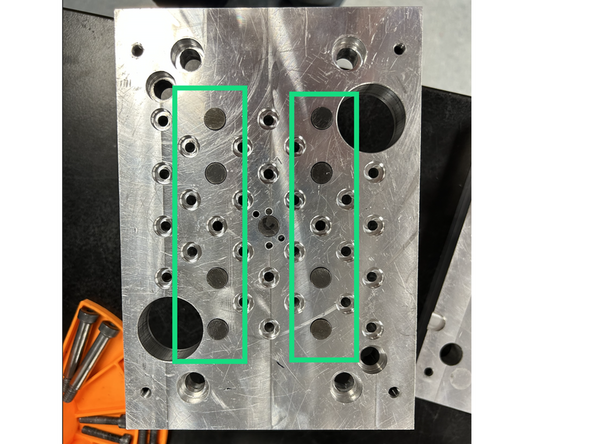
The final pin plate assembly should look like the second image.
-
-
-
Insert the gasket into the pin side mud plate. Ensure that the holes line up for the pins if your gasket has pin holes, and that the threaded holes are free of any material.
-
The gasket you use may look different than the one pictured but the process is the same.
-
Bolt the pin side mold into the mud plate using M6-30 bolts.
-
If there is considerable resistance, do not continue tightening. Unscrew the bolts and check that nothing is in the threads and that the mold is properly aligned. The threads are aluminum and will be damaged by excessive force.
-
-
-
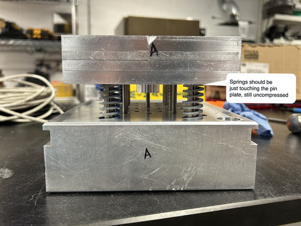
Insert the 4 springs into their pockets in the back of the ejection pin mud plate.
-
Slide the pin plate assembly into the mud plate. The thick guide pins should line up with the springs and slide into their larger respective holes. Stop once the pin plate is sitting on top of the springs but not compressing them. The plate may end up slightly unlevel, which will be corrected in the next step.
-
This process can be difficult with so many parts needing to align. The easiest process we've figured out is to place the pin plate on the table and then put the mud plate on top, wiggling it to seat all the pins using the weight of the mud plate. Once the pins are seated, it can be flipped and pressure can be applied from the pin plate top.
-
Excessive force and hammering should not be used unless necessary, since this can bend or damage the ejection pins, bushings, and mold.
-
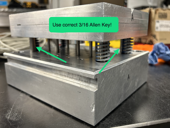
Tighten the two shoulder bolts down into the respective corner holes until they are fully seated. The pin plate should now be fully parallel with the ejector pin plate and the springs should be slightly compressed.
-
The shoulder bolts use a 3/16 Allen key, unlike the rest of the M6 bolts in the assembly! The same metric Allen key will fit in the shoulder bolt but it will strip it out over time.
-
-
-
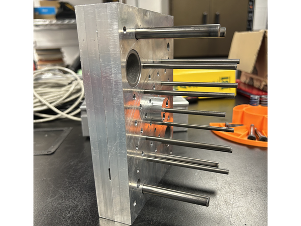
The two sides of the molds are now assembled. They can be inserted into the machine and used.
-
The process for disassembly is the exact same, but in the reverse order. The only change is that all of the pins do not need to be removed if the mold insert or pin pattern is not being changed.
-
It is sometimes easier to remove the pin plate from the mud plate if the mold insert is first unscrewed rather than being unscrewed after the pins are removed.
-