
Introduction
This guide will show you how to convert an STL file of an object into a job file ready to be printed on the Nanoscribe.
-
-
Open the DeScribe software by clicking on the desktop icon or searching for the program in the start bar.
-
-
-
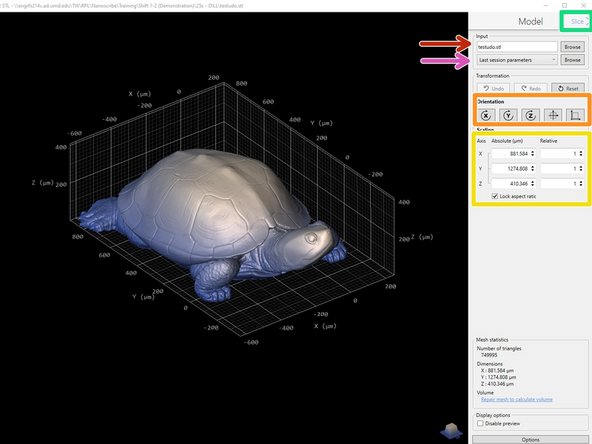
Go to File>Open and select an STL file. The user interface should open with an image of your part.
-
When files are imported, DeScribe interprets the dimensions' units as microns (e.g. if a file is exported with mm units, a 20 um part will be imported into DeScribe as 0.02 um). Design your part accordingly to avoid potential loss of resolution from having to scale up the model.
-
-
-
Import a different STL file here, if necessary.
-
Select the slicing parameters that match your intended objective and print method (solid vs shell and scaffold)
-
The default 63x and 25x recipes should already be loaded, but you may need to download the 10x parameters from NanoGuide.
-
Orient your part so the bottom is on the XY plane representing the substrate (Z=0).
-
Rotation is only possible in increments of 90 degrees
-
If necessary, scale the part to account for discrepancies in exported/imported units.
-
Click the Slice button in the top right corner to move on.
-
-
-
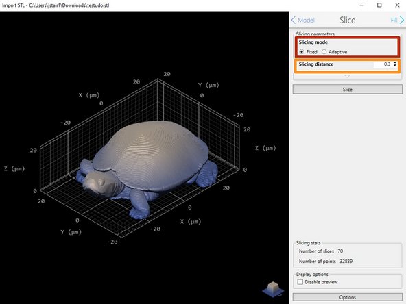
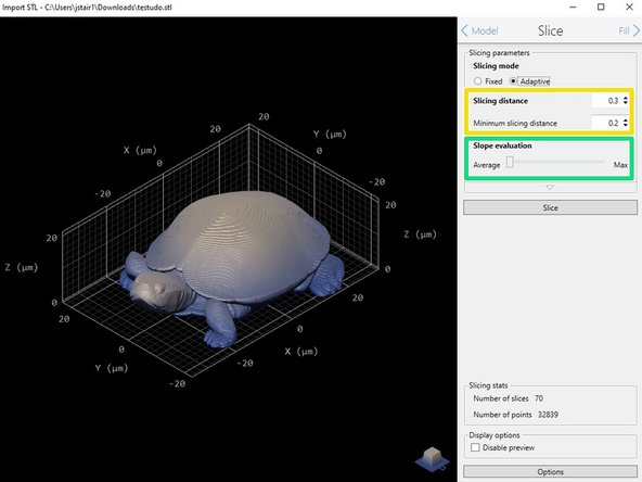
Choose your desired slicing mode.
-
Fixed uses the same slicing distance for each layer, and adaptive adjusts the slicing distance based on the slope of the part to improve printing efficiency.
-
The default values will yield the best results for standard prints, but you can adjust the slicing distance as necessary to better fit your part.
-
25x objective: 0.5 um - 1 um (up to 3 um)
-
63x objective: 0.2 um - 0.7 um (up to 1 um)
-
Enter the maximum and minimum slicing distance, if using adaptive mode.
-
Increase the slope evaluation as needed to improve resolution for local slopes (if the part is not rotationally symmetrical).
-
-
-
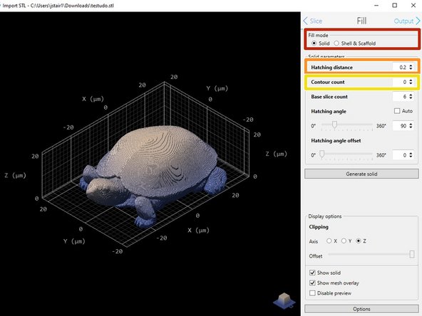
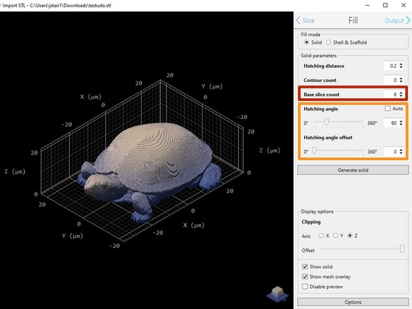
Select the desired fill mode. Solid is typical, but Shell & Scaffold may be used for larger parts to decrease print time.
-
Your fill mode in this step should match the fill mode you selected when choosing your slicing parameters in the first step
-
Hatching distance: the distance between each line in the laser path in the x-y plane
-
Contour count: 0-1+; contouring increases part smoothness, but greatly increases the print time
-
Hatching distance and contour distance (if applicable) will not be equal to the slicing distance, and may not be equal to each other. Use the default values for best results
-
-
-
Base slice count: base slices can be printed with a different laser power and scan speed (print parameters) to prevent burning at the surface of the slide.
-
For printing on glass slides (63x and 25x) using different print parameters for base layers is optional. Base slice count should be 2um divided by the slicing distance. This is reflected in the default values.
-
For printing on silicon wafers (25x and 10x) using different print parameters is necessary for base layers. Base slice count should be 10um divided by the slicing distance. This is reflected in the 10x default values. 25x base slice count must be altered since silicon wafers are not part of the standard print set.
-
Hatching angle: choose auto for the fastest route or 30-60 degree offsets for increased structural strength.
-
-
-
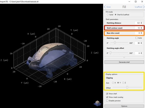
Shell contour count: the number of solid outer layers, replacing the contour count from solid fill. Shell thickness is equal to Hatching distance * Shell contour count.
-
Shell contour count should always be equal to the default or higher (12 for the 25x and 63x, 18 for the 10x). Fewer layers will result in loss of shell integrity.
-
Base slice count: the (minimum) number for solid layers at the base of the print. A thicker base can increase adhesion in Shell & Scaffold mode. Settings for printing with different print parameters from Step 6 still apply.
-
The number of solid layers at the base of the print may be higher than the input Base slice count. This is because the thickness of the base (number of solid layers * Slicing distance) must be equal to or greater than the Shell thickness.
-
When printing with silicon wafers (25x and 10x), be careful when adjusting the base slice count since you will need to use different print parameters for those layers.
-
Clipping: can be used to view a cross section of the part using a plane cut. Offset can be moved along the selected axis using the slider.
-
-
-
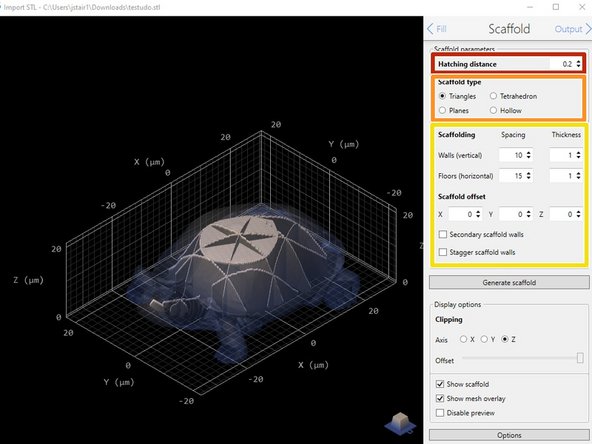
For Shell & Scaffold prints, set the scaffold hatching distance to match the shell hatching distance.
-
Choose your preferred scaffold type. Triangular scaffolds are typical, but the tetrahedron or planes options may be better choices depending on the geometry of your part.
-
Do not print hollow structures. Liquid resin does not provide structural support after printing and the walls/ceiling will bow or collapse.
-
Adjust the spacing, thickness, and location (scaffold offset) of the scaffold to best support your print.
-
Scaffold settings should only be adjusted to add more support, i.e. decrease spacing. If there is less scaffold, i.e. larger spacing, the wall or ceiling of your print will bow or collapse.
-
-
-
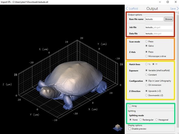
Select a file name for your exported files; the best practice is to only modify the Base File name, which will keep nomenclature consistent throughout all of the files associated with the part.
-
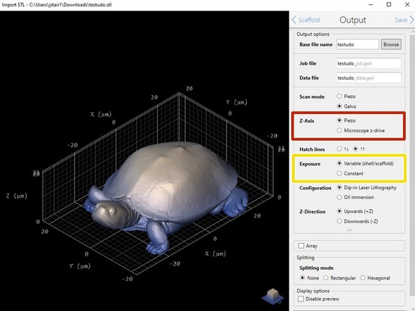
Set the scan mode to Galvo and the Z-axis to Piezo.
-
Adjust the print parameters as needed:
-
Hatch lines: Alternating is faster than one-way hatching, but runs the risk of burning the edges of the print
-
Exposure: Constant is sufficient; variable can be used if it is necessary to modify base layers or the scaffold of Shell & Scaffold prints.
-
Configuration: This flips the part orientation based on print mode. Can be modified later as well.
-
Z-direction: Leave at Upwards (+Z), completely independent from configuration. Cannot be modified later.
-
Select Array if you want to print multiple parts at once. Can't be used if your part is larger than the effective print area of an objective.
-
-
-
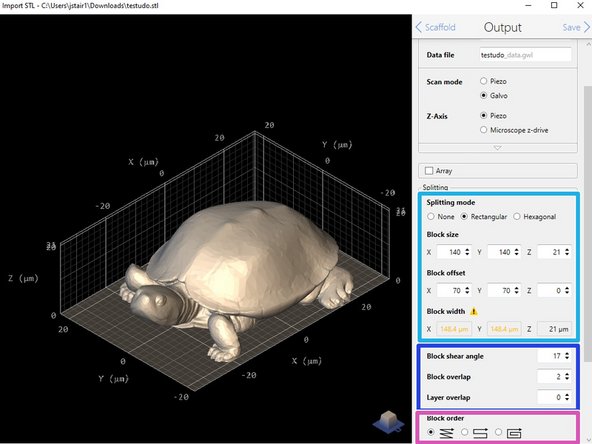
Rectangular splitting mode is easier to use than hexagonal, but hexagonal is more efficient for printing large parts.
-
Reduce block size until the yellow text and caution sign next to block width are gone.
-
Adjust the block offset as necessary to avoid stitching (block edges) near critical features.
-
Block shear angle is automatically adjusted, but block overlap can be increased for Shell & Scaffold prints.
-
The block order mode can be adjusted to further fine-tune the printing process.
-
Lexical has the highest precision and an option for backlash correction, and is good for high-resolution prints where less stitching error is desired.
-
Meander and Spiral reduce stage movements and decrease print time, especially with prints that have a large base. Both have errors in block placement due to lack of backlash correction.
-
-
-
Microscop z-drive should be used for tall parts on the 10x.
-
The microscope z-drive allows for taller continuous blocks, but has a larger error than the piezo. It can only be used for the 10x, because the height of the voxel compensates for the error.
-
Variable exposure should always be used for the 10x because the base layers and scaffold (if applicable) require significantly different exposure levels than standard solid hatch lines.
-
Variable exposure should also be used with the 25x when printing on silicon wafers because the base layers will also need altered exposure levels.
-
-
-
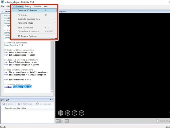
Select Generate 3D Preview to view the print time estimate.
-
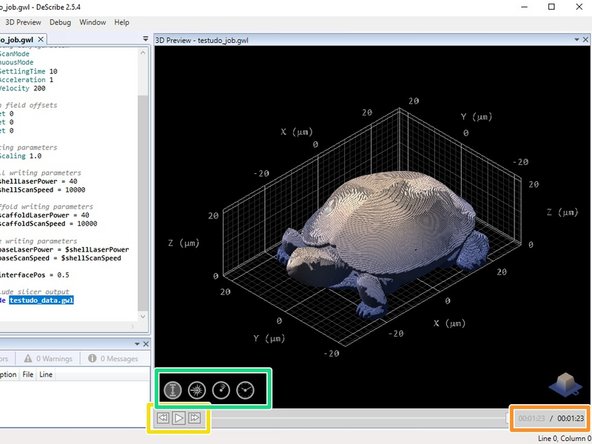
The time estimate is located in the lower right-hand corner (in hh:mm:ss format).
-
Click play to preview the laser path. This is important for checking for any floating blocks.
-
Choose what information you want to include in the print preview. The preview can be viewed in terms of print height, laser power, laser speed, and time.
-


Cancel: I did not complete this guide.
One other person completed this guide.