
Introduction
This guide explains the process to turn point cloud data from a scan to an .stl with Artec Studio.
-
-
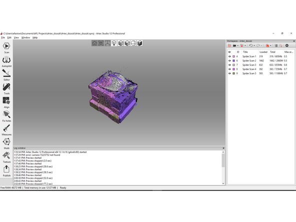
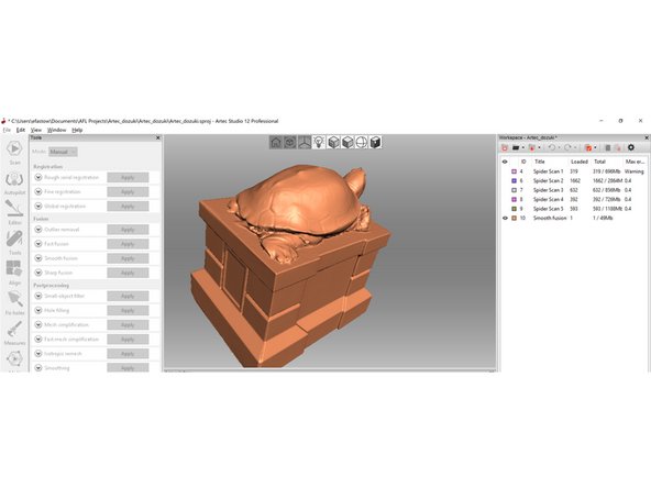
This guide begins with scanning already completed with the Artec Space Spyder.
-
Note that we have created multiple scans denoted on the right side of the Artec Studio Software. Using this tab we can toggle the scan visibility and select specific scans.
-
For very simple scans, select the autopilot tool on the left side menu. This will walk you through the steps to produce a solid mesh from a point cloud.
-
In general, the process given by this guide follows these steps: 1) clean up scans by deleting points generated in error 2) align scans to each other 3) fuse scans into a solid mesh
-
-
-
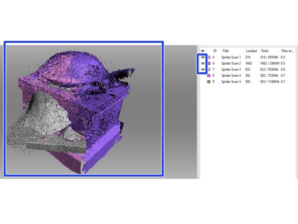
Use the work space menu on the right to only set one scan visible. This will make the process of cleaning up a scan much easier and remove the risk of deleting desired features of other scans.
-
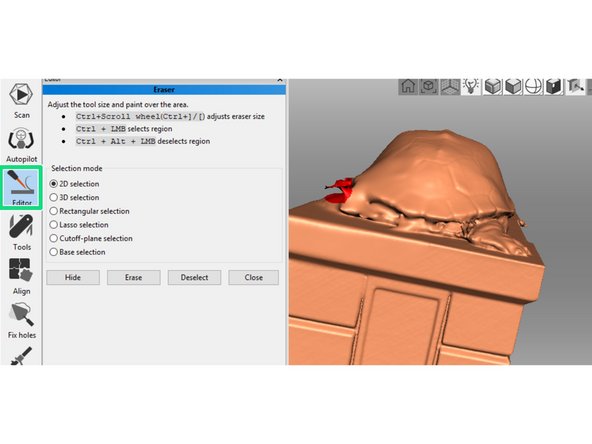
Open the editor menu and select the eraser tool.
-
Use the key and mouse combinations highlighted in the yellow box to select undesired regions of the scan.
-
In this example, we have selected a region of desk accidentally scanned.
-
After selecting all of the undesired features, press the erase button to delete them.
-
Repeat this process for all of the individual scans
-
-
-
This step discusses the process of aligning multiple scans together. This is the most difficult step of the guide and will likely take the most time by far.
-
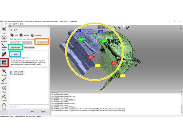
Open the align tool on the left side menu
-
Click the "New Pair" button. This allows you to drop points that mark features both scans have. The software will line up these points to align the scans.
-
Click on distinct points that both scans capture to drop a pair of alignment markers. The more distinct these points are (e.g. a corner is more distinct than a bump on a smooth face) the more accurate the alignment will be.
-
Select the "Align Markers" button to check the accuracy of the alignment generated by the pairs. If this alignment does not look accurate, edit the existing marker pairs or drop new ones.
-
Once the alignment looks accurate, click "Align" then "Apply" to align the scans.
-
Applying alignment changes to two scans, toggle the visibility on a third. You should now have three scans visible, two aligned to each other and one un-aligned. Repeat the above steps to align the third scan to the other two. Keep repeating this process to align all scans together.
-
-
-
The final steps to generating a .stl from a scan is running an algorithm to build a mesh from the point cloud
-
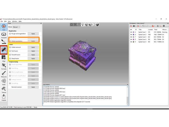
Open the "Tools" tab on the left hand menu. This has a few commands for building and editing meshes.
-
Run a global registration to set all points in the same global coordinate system. This step is not necessary, but highly recommended.
-
Run a fusion algorithm to covert the point clouds to a mesh. The algorithm chosen depends on the nature of the scan. In this example, I used "Smooth Fusion".
-
Fast Fusion: This is the least powerful algorithm that will not produce a manifold (printable) mesh. Only use this for very large scan jobs where RAM is at a premium.
-
Smooth Fusion: This is a more powerful algorithm that can produce manifold meshes. It automatically applies a smoothing features, so models lose details on the order of 100 um, but have a much better surface finish
-
Sharp Fuison: This is the most powerful algorithm that uses the most RAM. The sharp fusion algorithm produces the highest resolution mesh and preserves more details.
-
If the model requires more post processing, use the tools in the "Editor" window to clean up the model. In this example, I had to erase a feature generated in error.
-


One Comment
Similar to the advanced leo guide, we should be teaching them skills instead of processes. Processes can be handled as courses filled with skill guides. We want technicians to understand each tool on their own, so that they are able to apply them in situations other than this prescribed one.
Evan Hutzell - Resolved on Release Reply