Introduction
Post processing your 3D scans allows you to convert point cloud data into a STL or Mesh object so that you can print them or work with them in CAD, respectively.
The workflow for post processing can be seen in the flowchart inside the Geomagic Wrap booklet, which is also a good resource.
In general, the process includes:
- Scanning the target object from multiple angles
- Cleaning each scan by removing captured surfaces not part of the target object
- Aligning the scans from different angles
- Merging the aligned scans into a single mesh
This guide introduces the fundamentals of post processing 3D scans with Geomagic Wrap.
Quick tip: although you can do a lot with post processing, it is always easiest when you have quality scans to work with.
-
-
On the right is the toolbar where you can find ways of selecting and viewing your scan
-
Near the bottom there are 3 modes: select visible, select through, and select backfaces (yellow)
-
Select visible only captures areas that are seen, if there is texture on the data it will miss sharply angled points
-
To rotate around your scan hold and drag the scroll button. You can set the center of rotation by right clicking the part -> set rotation center -> click the new center on the part
-
On the top there are self explanatory tabs. When you click on an action in a tab it will usually lead you to open a dialog on the left
-
If applicable, make sure to apply -> OK to ensure those actions actually get applied
-
Most actions in Geomagic Wrap can only be undone (ctrl z) immediately after you have done it. It is best practice to save your work at important checkpoints
-
-
-
During the scanning process you may capture data that is not a part of your target
-
Select the unwanted data using the tools on the right hand side. Some recommended ones are: the rectangular, lasso, and paintbrush selection tools
-
For this I would suggest the modes select backfaces and select through
-
Additional selections will be kept automatically. If you want to deselect data you hold Ctrl then deselect specific areas or right click -> clear all
-
Delete the unwanted data. Continue until the scan is mostly clean
-
Fn -> F2 to hide the other groups of scan data
-
-
-
Once all scan group have been cleaned, you need to combine your scan setups so that the data is aligned
-
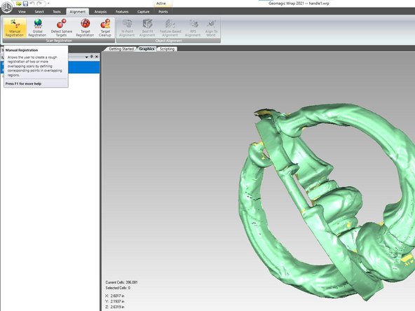
Select 2 groups you will be working with in the model manager and go to alignment -> manual registration
-
Select one group to be fixed and another to be floating
-
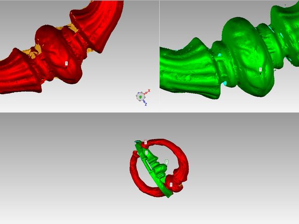
Align the scans by selecting a point on the fixed scan and then selecting that same point on the floating scan to register that they are the same spot
-
Try to select points that are surrounded by other data and are along different parts of the scans
-
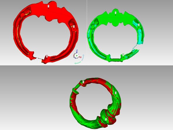
After selecting 3-4 points the image at the bottom half should depict the alignment of the scans
-
If this does not happen or the combined scan looks strange, clear the points by actions -> clear and start over
-
Once you are satisfied click Ok to save the alignment
-
-
-
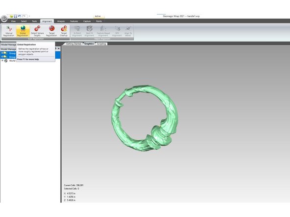
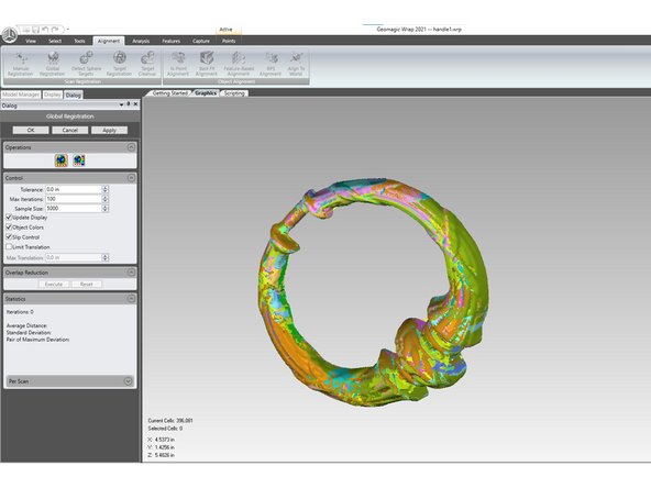
After aligning the parts together, you will need to further polish your merge by global aligning the part
-
Press apply 4-7 times until colors look sufficiently combined then press Ok. This merges the point data to fine tune your new part
-
You will notice that there are still large solid blocks of color after this. This is because so far you are only aligning the scan data within each group. This will be fixed in the next global align.
-
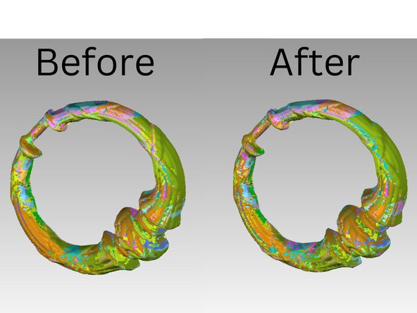
Navigate to the model manager. Right click on each group and break the group. Then select all the scan data by selecting the first scan -> holding shift -> selecting the last scan. Right click and create a new group
-
Go through the global alignment process again. Now you will see that most of the scan data (colors) have become more dispersed and even
-
-
-
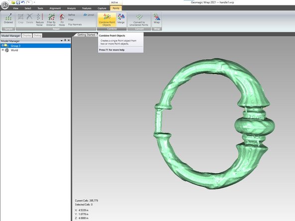
Combine the point objects to create a single object out of your scans
-
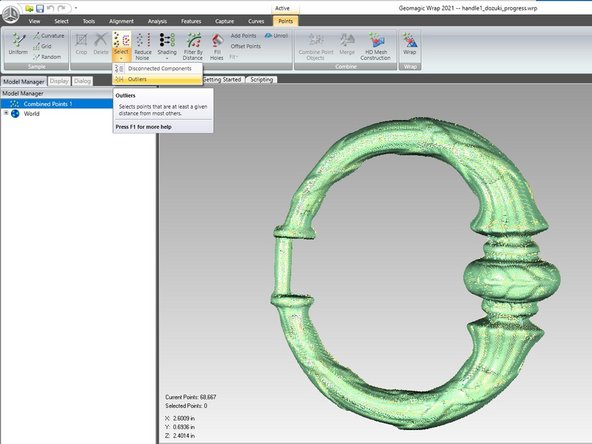
Select disconnected points by going to Points -> Select -> Disconnected Components. Generally the default settings are fine. Click Ok and delete the points which it has selected
-
Select points that are outliers by going to Points -> Select -> Outliers. You can change the sensitivity, but generally the default is fine. Then click apply and Ok. Now delete the selected outliers
-
-
-
During scanning you may have captured unnecessary data. These steps will help increase part quality and operation speed by getting rid of redundant data. However you have to be careful to not compress your scans too much
-
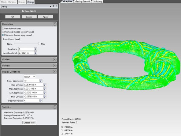
Under Points -> Repair -> Reduce Noise, which compresses points to make a smoother final product. There are 3 forms of noise reduction. Free-form is for organic shapes and the prismatic conservative retains sharper corners compared to the aggressive. To adjust how much noise reduction to apply, drag the slider
-
The statistics tab will show you how much the smoothing operation has changed your new part in comparison to the original
-
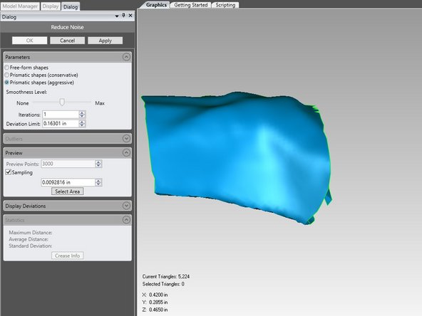
The preview tab allows you to select a certain part of the scan and see how the smoothing operation affects that section
-
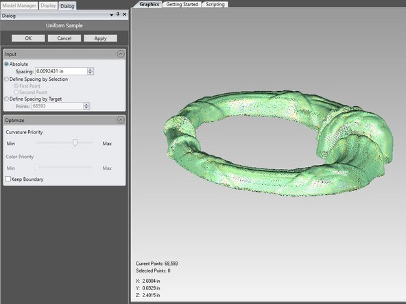
Uniform point sampling reduces the density of the point cloud without moving the points. Get there by Points -> Sample -> Uniform. In the optimize tab you can adjust the sampling algorithm to preserve more points around curves, which helps retain their detail
-
Absolute sampling defines space between points and deletes ones that are too close. You can usually stick to the recommended amount, or round up/down as you see fit
-
Define spacing by target lets you set a specified amount of points you would like the final scan to have. A larger scan will need more points than a smaller one. A good rule to follow is to at least round down to the nearest 10,000 on a small part and larger parts can be reduced further
-
It is always a good idea to reduce less at first, check the part quality, and then sample more if necessary
-
-
-
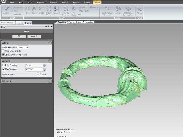
Wrapping the part converts the points to a polygon mesh cloud. Get here by selecting Points -> Wrap -> Wrap
-
If you did not perform a noise reduction, you are able to do so here. If you did, make sure noise reduction is set to None. Otherwise, it is fine to stick to the default settings
-
-
-
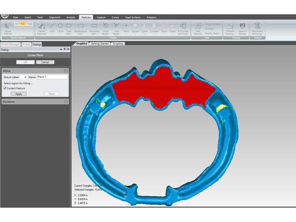
If you would like to set the scan at a certain place in the "world" aka have the scan close to the origin you will first need to create features: planes, lines, and points that will allow you to reference against the xyz coordinates
-
What types of features you define will depend on your scan. In this example, there will be a plane defining XY and a point for the origin. Generally, you just need to define enough features to constrain the scan
-
There are many different ways to define these features and you can find more information in the book. I will be showing 2 useful techniques
-
Features -> Plane -> Best-Fit allows you to define a plane based on a selection. A helpful selection tool to use is the crease-angle selection tool paired with select by angle mode in the menu on the right. You click and hold an area and move up to select surrounding data that are on a similar angle. Click apply to create your plane
-
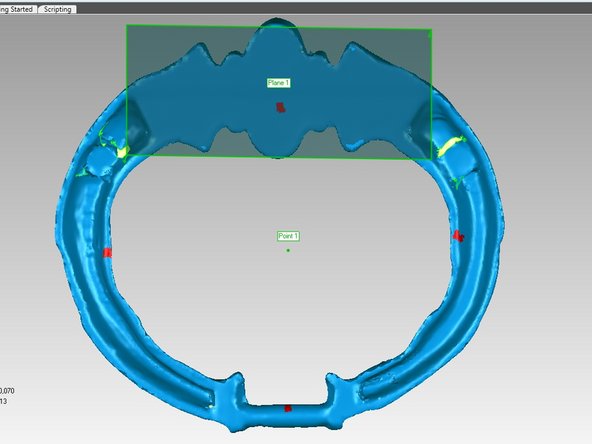
Features -> Point -> Centroid allows you to set a point depending on selected areas. Select data surrounding where you want the point to be then click apply. If your point is not right, select/deselect data until you are satisfied
-
In Alignment -> Object Alignment -> Align to World, you pair features and the world together. In this case the plane is set at the bottom of the part so it will need to be paired with the XY plane. You can also flip the plane if it is upside down. Then select the origin, point 1, and create pair to fix the center of the part to the origin
-
-
-
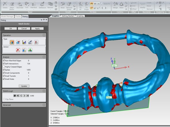
Select Polygons -> Repair -> Mesh Doctor to analyze the entire mesh for issues. Click Apply and then Ok to automatically fix these issues
-
You may notice green lines and yellow space in the mesh. This is where there was not enough scan data, leaving holes that need to be filled. To do this go to Polygons -> Fill Holes -> Fill Single
-
On the right of Fill Single, you'll notice 2 rows. The top row has 3 options: curvature, tangent, and flat. Choose the best setting that matches the data surrounding the hole. If you're unsure, tangent is always safe and you can undo a hole fill
-
The bottom row has the options: complete, partial, and bridge. Complete fills the entire hole, whereas partial fills only some and bridge creates a bridge within a hole. These last 2 are used when a hole spans very different types of data (flat and curved) so that you can apply different settings to different parts
-
To use a bridge fill, click and drag along the edge of the hole where you want the first part of the bridge, then click and drag on the other side. To use the partial fill, click and drag along the section you would like filled
-
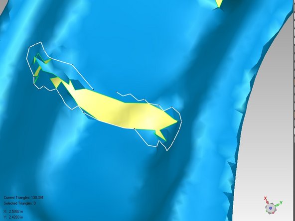
When you have a lot of complicated/unwanted geometry around a hole or even on a surface you may want to delete it and then fill the hole. Here, the polyline selection tool is recommended. Select points around the target area and the tool goes along the edges of triangles so that any angular polygons are selected. Right click to finish then delete
-
When you get more comfortable, you can use the Fill All tool, however it is recommended that you individually fill complex holes
-
-
-
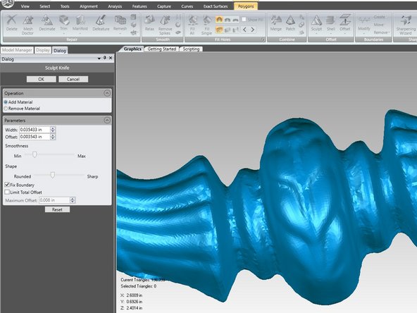
If you see areas on your part that are not what you would like, there are a variety of tools to reshape your data
-
For these operations it may be helpful to change the lighting to better see the polygons. To do this, go to the toolbar on the right, the 3rd icon from the top, and click flat shading. Or go to View -> Settings, and change the shading to flat
-
In Polygons -> Offset -> Sculpt -> Sculpt Knife allows you to click and drag over areas to change its surface. Notable features allow you to add/remove material and change smoothness and shape.
-
In Polygons -> Smooth -> Sandpaper, the sandpaper tool allows you to click and drag to reshape areas of the part. If you want to start over, simply click reset. Adjust the strength/operation to what looks best
-
There are also many other operations that can be found in the booklet
-
-
-
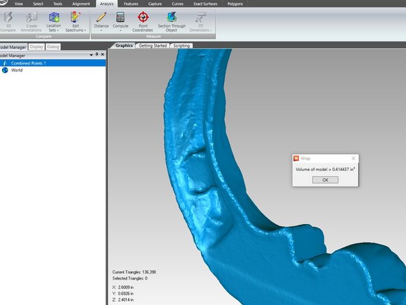
When you are satisfied with your post processing, you will need to check that the part is water tight by going to Analysis -> Measure -> Compute -> Compute Volume
-
If you get a number for the volume, your part is ready to export as an STL. Go to file -> save as to export your finished product
-
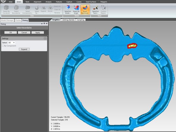
If there is not a number, there are still geometries/holes that need to be fixed. You can find them by going to Select -> Select Boundaries. Apply and expand the selection 2-3 times to highlight more of the hole. Then you can go to View -> Settings -> View -> Selected Only.
-