Introduction
Insight is the native slicing software of the Fortus line of Stratasys printers. It slices and writes toolpaths for a 3D object file such as an STL, resulting in a CMB file that can be interpreted by the job creation software. Many of the key features of Insight have since been replicated in GrabCAD Print, but Insight provides more functionality and remains the more powerful program.
This guide covers the basic operation of Insight, including part manipulation, modeler configuration, slicing, and default toolpath generation. Always ensure that your version of Insight is up to date; as of 2019, you must use version 13 or newer to avoid print failure.
-
-
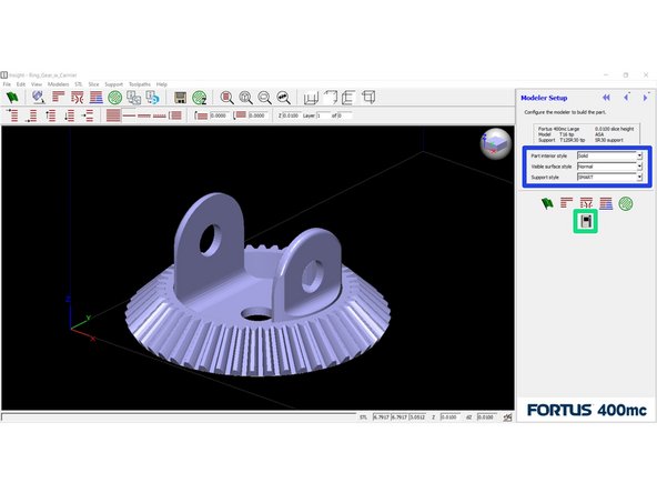
This is what you will see when you first open Insight. A few key areas have been highlighted
-
These are the most commonly used functions in preparing a file. This guide will discuss them in more detail in later steps, or you can hover over each for a tooltip description
-
This is the current modeler configuration, including modeler type, model and support materials, tips, and slice height
-
These functions help you navigate through the model layers once it has been sliced
-
These icons change which layers are visible; you can view all layers, a single layer, two adjacent layers, or a selected region
-
These icons are view presets that change the viewing angle in the preview window
-
This text bar will display information about the last function that Insight performed
-
-
-
Insert a file, either by dragging and dropping it into the window or using File > Open from the menu bar
-
Ensure the units are correct
-
By default, Insight interprets dimensions in inches. If it detects that a part would be very large, however, it will prompt you to convert to millimeters instead
-
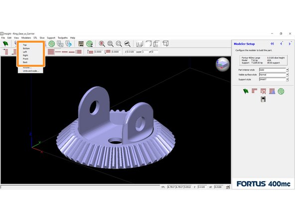
To change the unit system after importing an STL, navigate to STL > Units and Scale and select your desired units
-
-
-
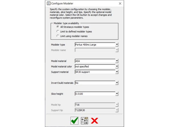
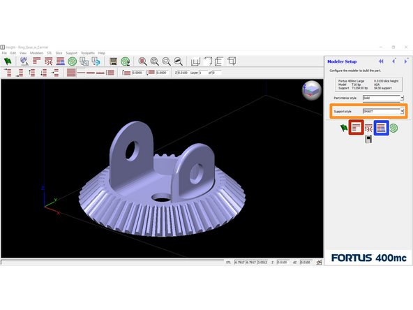
Ensure the modeler configuration matches your intended setup
-
The machine should always be Fortus 400mc; select model and support materials as desired
-
Choose the part options, found in the three drop-down menus on the right side of the screen
-
Part interior style determines the infill density. "Solid" is 100%, "Hexagram" is 54%, "Sparse - double dense" is 36%, and "Sparse" is 18%
-
Visible surface style can be changed to improve the aesthetic quality of exposed surfaces. "Enhanced" will make the toolpaths of exposed surfaces narrower and more tightly packed
-
Support style will be set automatically when the model material is selected, depending on the recommended setting
-
-
-
For simple parts, you can orient a specific face on the part to one of the datum planes
-
The Orient Face icon is located in the toolbar just below the View menu
-
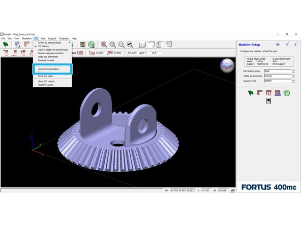
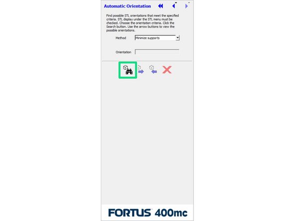
More complex parts can be automatically oriented
-
Go to STL > Automatic orientation to view orientation methods
-
Insight will calculate the optimal orientation(s) for the method you've selected, allowing you to cycle between them and choose one
-
-
-
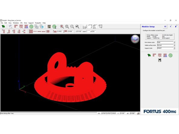
Click the Slice button to divide the part into discrete layers
-
The image preview in the main window will update to show the sliced model
-
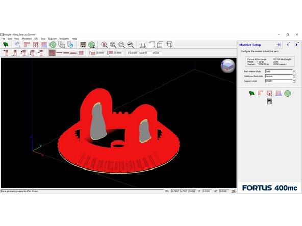
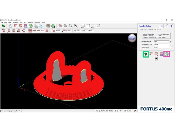
Click the Support button to generate support structures
-
Again, the preview will update to show the support structures
-
This is a good opportunity to inspect the support structures and make sure they look appropriate
-
To change the support style, you can just select a different option from the menu and click the Support button again
-
-
-
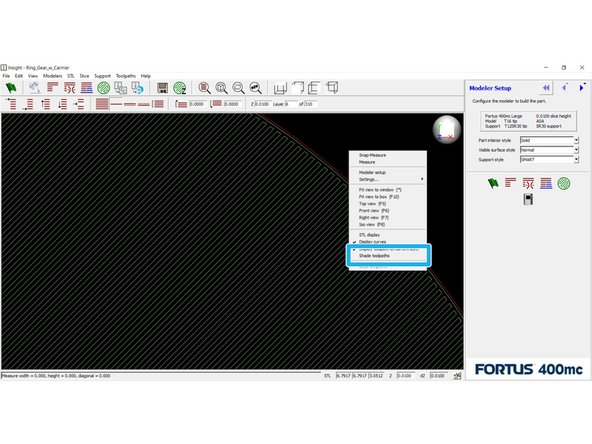
Click the Toolpath button to generate toolpaths for each layer
-
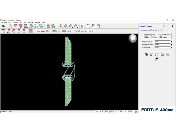
Right click anywhere in the preview window and select Shade toolpaths to get a better view
-
You can use the Page Up and Page Down keys on your keyboard to move throughout the part and inspect key features
-
Click the Finish button to complete all remaining processes and save the CMB file
-