
Introduction
This is an advance tutorial for Romer Absolut Arms 3D scanner. It will teach how to scan multi color and hard to scan object. The tutorial assume that the users have completed the beginning tutorial and have sufficient skill to operate the scanner.
-
-
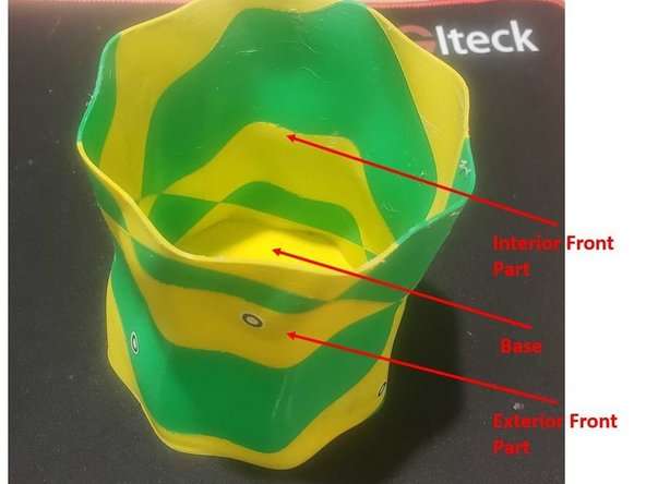
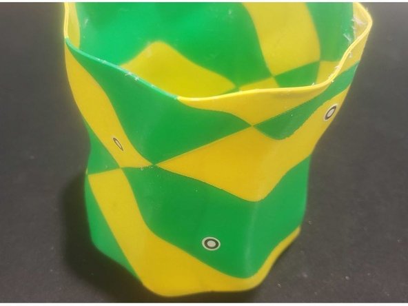
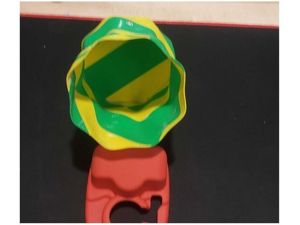
In this tutorial you will working on scanning of a pens case (See figure)
-
Before reading the next point, try to guess what are the challenges in scanning this part
-
Challenges:
-
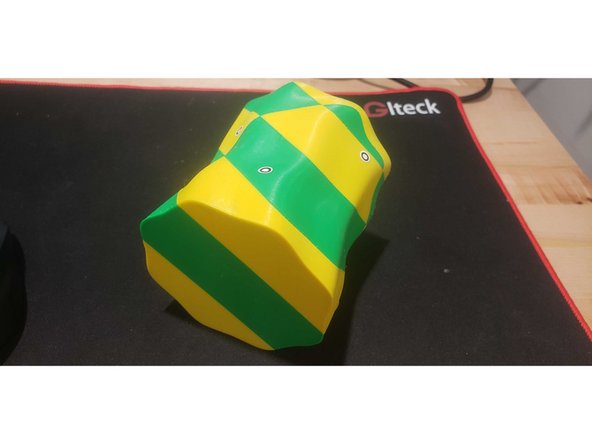
Multi color
-
Repeated pattern
-
You need to scan both interior and exterior that are separated by a thin wall
-
-
-
For scanning part with repeated feature, marker can be added to help for the scanning and alignment
-
Sticker marker is available for this purpose
-
Add the stickers in both the interior and exterior structure at a random manner
-
-
-
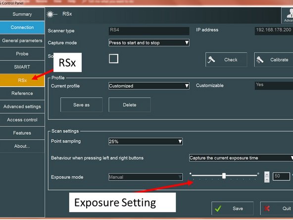
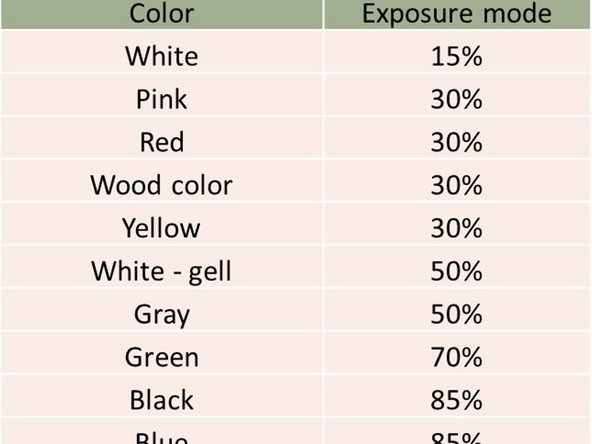
For scanning multi color part, you will need to adjust the exposure limit accordingly via RDS control panel
-
First you need to start by setting the exposure which is suitable for one color (Green)
-
You will need to switch the exposure limit back and forth to scan the entire case
-
-
-
Placed the pens' case into the scanning table
-
Make sure that your exposure limit is set to scan green color
-
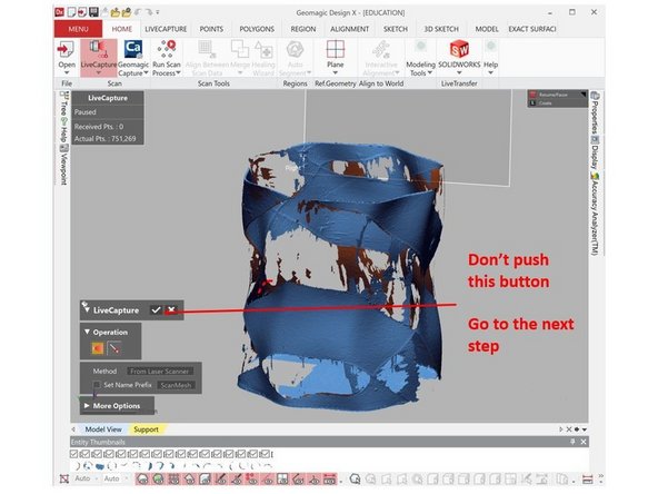
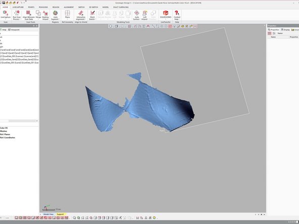
Start scanning the exterior front, interior front of the part, and the base of the case as shown in the figure. Note: Front is side that facing you
-
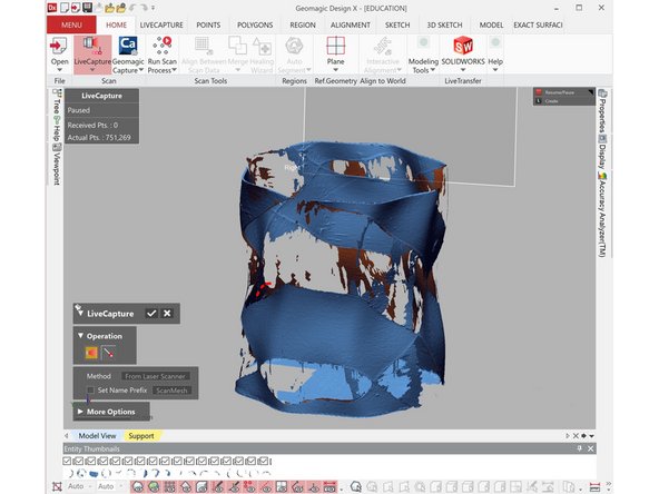
You will get a partial scan of the object (See figure)
-
You don't need to force scanning the back section as you may end up with misaligned scan result or scan with a lot of noise
-
After you finish scanning the green color section of the object, don't push the Ok button (Don't turn on the mesh buildup wizard)
-
-
-
Open the RDS control panel and switch the exposure limit to the one suitable for scanning yellow color
-
Make sure to close RDS control panel
-
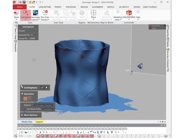
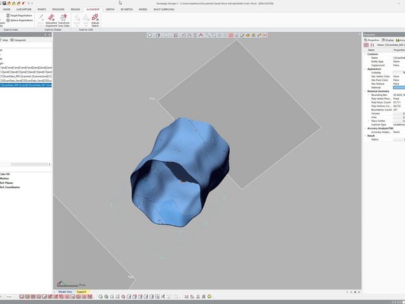
Continue running the scan, but now try to scan the section with yellow color
-
You should be able to get a complete scan with both color now (See figure)
-
You don't need to force scanning the back section as you may end up with misaligned scan result or scan with a lot of noise
-
-
-
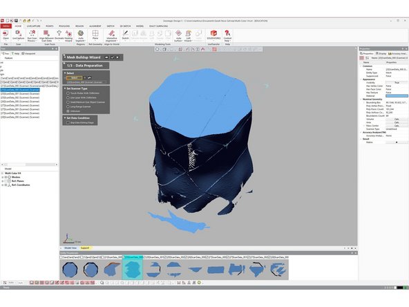
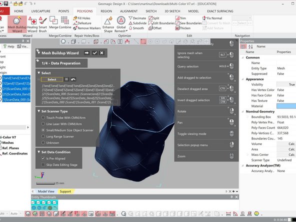
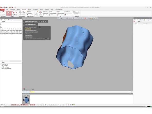
When finished, run mesh buildup wizard for combining the mesh file
-
Normally, Hexagon Arms should produce results that are well align
-
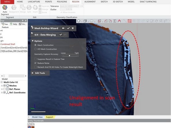
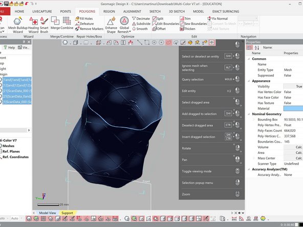
However, when scanning a part with thin and repeated feature like this, there are chance of that there are some miss-alignment on the results (See figure)
-
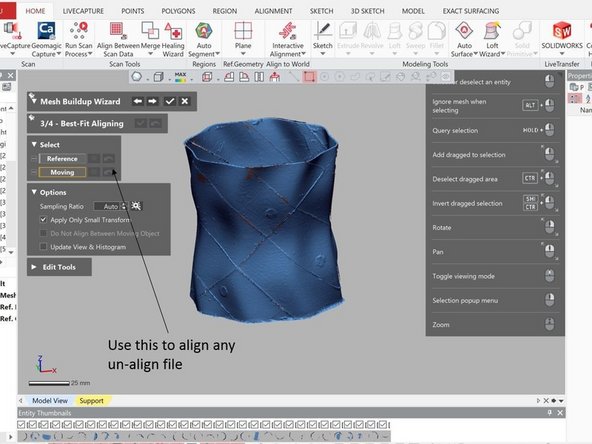
Use the Best-Fit Aligning (The third under Mesh Buildup Wizard) for aligning of scan results which are not align well
-
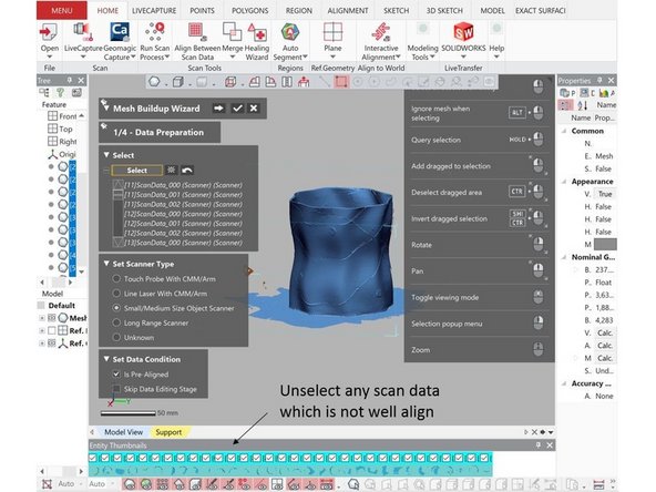
In worst case scenario when the misalignment cannot be resolved, unselect the misaligned scan file under Data Preparation (The first under Mesh Buildup Wizard) and continue the file combining process without it
-
After you finish with the Mesh Buildup Wizard, you can delete the unselected file
-
-
-
Rotate the object so that you can scan the object from different angle
-
Redone step 4 to 6 to get a scan of the object from different angle
-
Make sure that there are common scan area between the scans to allow for alignment
-
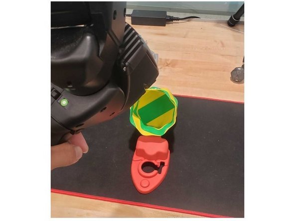
If you face a challenge scanning the interior section, it is recommended to laid down the part in the table with a support support structor underneath so that you scan scan it in an angle (See figure)
-
-
-
Turn the part upside down so that you can scan the bottom section of the base
-
Follow the procedure explained in step 4 to 6 to scan the bottom section of the base
-
Make sure that there are common scan area between the scans to allow for alignment
-
-
-
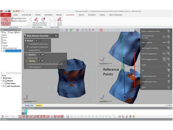
Performed part alignment by using the marker as reference points for the alignment
-
Make sure to check carefully if both scan results have been align properly. Due to the repeated feature and thin wall, the part alignment may not working properly. If you don't get a good alignment, redone the process by adding more reference points
-
When you done, analyze the scan result for any missing scan. If you found any rerun step 7 and 8 to get a complete scan
-
-
-
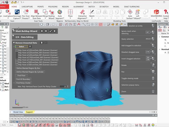
Use Mesh Buildup Wizard for combining multiple scan results
-
Before running the mesh buildup wizard save the file under different name. You may need to go back depend on the result
-
Run the mesh buildup wizard to combine the mesh file
-
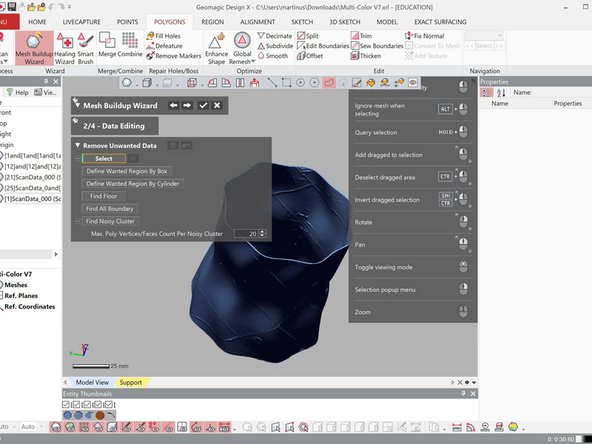
Use Data editing to remove any noise or unwanted scan
-
Use Best fit alignment if there is still misalignment between scan data
-
-
-
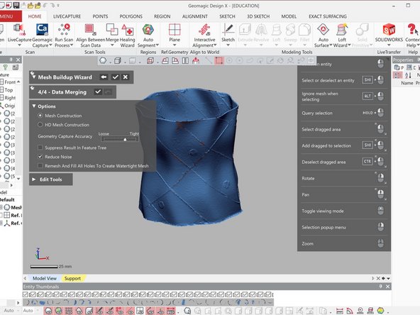
Use HD Mesh Construction for merging the scan results
-
You may wat to try different combination level of HD filter, Noise reduction level, and Fill Holes
-
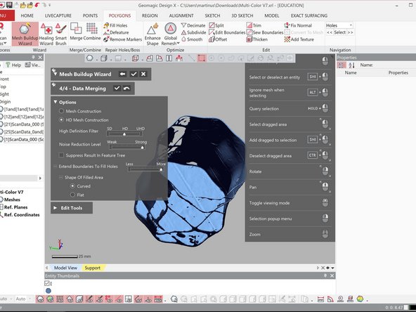
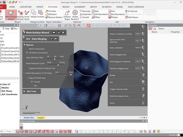
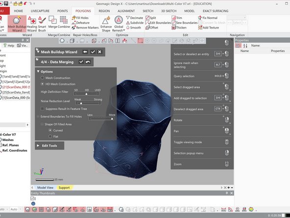
Below are some example of the merging result based on different noise reduction level
-
Strong noise reduction level => Too much noise is removed. You may see a lot of holes on this result
-
Weak noise reduction level => You most likely will get a watertight result. However, the surface may be a bit rough
-
Medium noise reduction level => You will get a result in between
-
If you find some small inaccuracy in the scan, don't worry the next step will explain how to deal with those
-
-
-
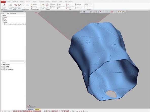
If there is small hole in the combined result, as shown in the figure, you can use the fill hole option
-
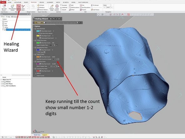
Before running the fill hole option, you need to run the healing wizard
-
The healing wizard can be access via Polygon > Healing Wizard
-
Select the scan data where you want to apply the healing wizard. Then click the check mark
-
If you get a warning saying that the software is failed to heal some singularities select try again
-
Keep running the healing wizard until the count showing a small number (1-2 digits). If you no longer have option to select try again, you can rerun the process
-
The fill hole option can be accessed via Polygon > Fill Hole
-
Select the boundary of the holes. Then click the check mark
-
-
-
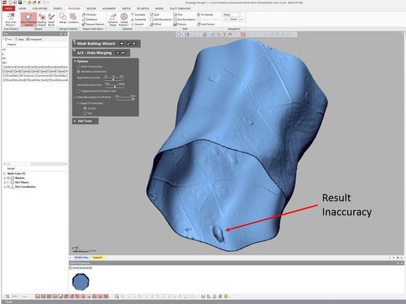
If you see a small bump on the combine scan as shown in the figure, you can erase the bump and use fill hole option to fill the hole
-
To erase the bump you need to re-run the mesh buildup wizard.
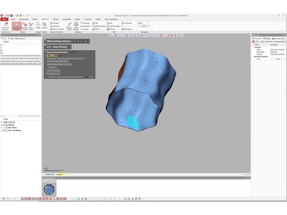
-
Use the data editing feature to remove the bump
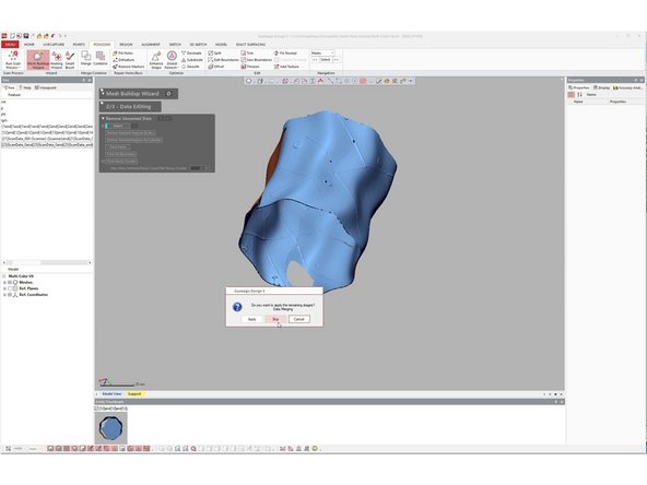
-
After you remove the bump, select the check mark under mesh buildup wizard without going through the data merging process
-
When asked "Do you want to run the remain stage?" select skip
-
Use the fill hole method explained in the previous step
-
-
-
In case if you have a large hole or bump where the fill hole option cannot fill accurately, you will need to re-scan that particular area
-
For re-scan, it is better to start using the file before they are combine. If you already perform a parts combine and you use the file for another combine, you will lose accuracy. Remember the file you save at step 9 before you do the part combine.
-
If you have a bump you will, need to delete the area where the bump will be (See previous step for more detail about the deletion process). As now you are using un-combine model, you may want to open the combine file side by side to have a better idea where the bump location
-
Run another scan on the area where you have the hole / bump. Then align the new scan with the old scan result
-
You don't need to scan a large portion, just focus on the region that need to be re-scan
-
Rerun the mesh buildup wizard to combine the scan
-


Congratulation you have learn the advance skill needed to operate Romer Absolute Arms 3D Scanner
Congratulation you have learn the advance skill needed to operate Romer Absolute Arms 3D Scanner
Cancel: I did not complete this guide.
One other person completed this guide.