
Introduction
This is a tutorial for using a probe in Romer Absolut Arms for parts measurement. The tutorial assume that the users have completed the beginning tutorial and have sufficient skill to operate the scanner.
-
-
Scanning probes are a family of tools used to make images of surfaces and structures
-
They use a scan probe to scan back and forth over the surface of a sample
-
During this scanning process, a computer gathers data that are used to generate an image of the surface
-
Applications: (1) Part inspection, (2) Part measurement, (3) 3D Scanning
-
Romer Absolute Arms come with three Probes:
-
A 15mm probe (For center reference, not for scanning)
-
A 3mm probe (For scanning)
-
A 1.5mm probe (For probing)
-
-
-
Align the probe to the scanner
-
Turn the switch to lock the probe. You may need to apply some strength to lock the probe
-
Make sure that the probe is aligned to the ARM when turning the lock switch
-
Avoid touching the tip of the probe
-
After the probe is locked, turn the switch on the back of the ARM to the left. This will switch the scanner to probe mode
-
See the figure for more detail on the instruction
-
-
-
Geomagic Design X software is used for operating the probe
-
To use the probe select LiveModel under Menu
-
There are 4 modes for using the probe
-
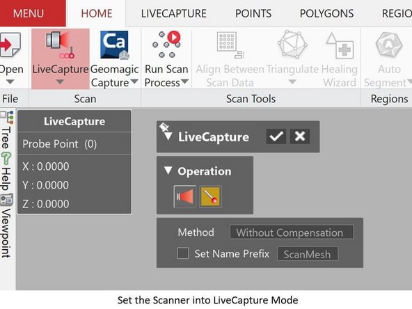
LiveCapture for creating mesh/point cloud data
-
LiveAlign for parts alignment
-
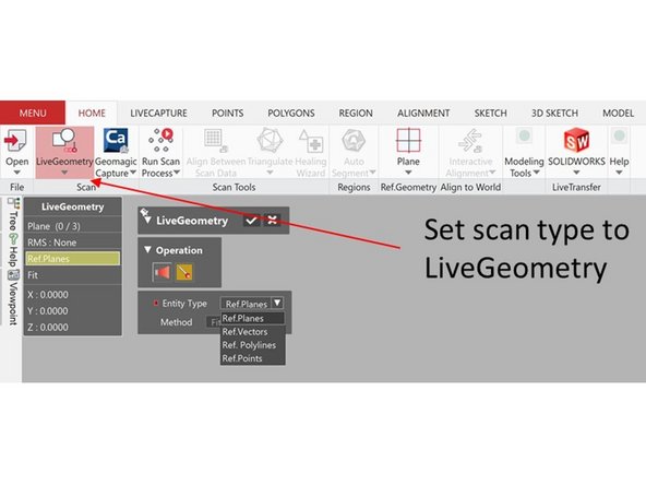
LiveGeometry for creating reference geometries
-
LiveModel for creating surface bodies, solid bodies, sketches, and 3D sketches
-
For each mode, select Probing under operation (See Figure)
-
-
-
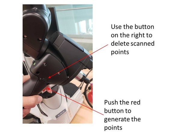
Push the red button on the handle to generate the points
-
Use the button on the right to delete scanned points
-
Use the button on the left to accept scanned points
-
This method is working for all of the probing modes shown in the previous step. You can try these on the next step (Step 5)
-
-
-
Set the scan mode as LifeCapture to create Mesh/Point Cloud data
-
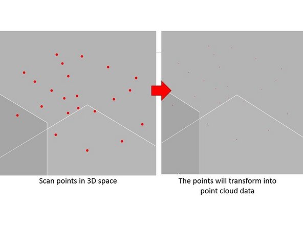
Scan multiple points in 3D space by using the probe
-
By accepting the scan results, the points will be transform into point cloud data
-
-
-
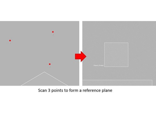
Set the scan mode as LiveGeometry
-
Four types of reference geometries can be created:
-
Reference plane => Scan 3 points to form a reference plane
-
Reference vector => Scan 3 points to form a reference vector
-
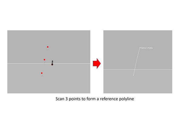
Reference polyline => Scan 3 points to form a reference polyline
-
Reference points => Scan 3 points to generate a reference point at the center of the 3 points
-
-
-
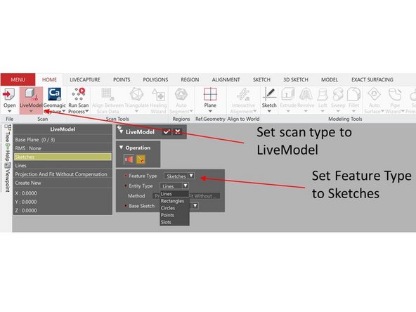
Set the scan mode as LiveModel
-
Set feature type as Surface Bodies
-
Five types of surface bodies can be created:
-
Planes => Scan 3 points to form a plane
-
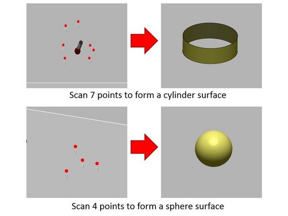
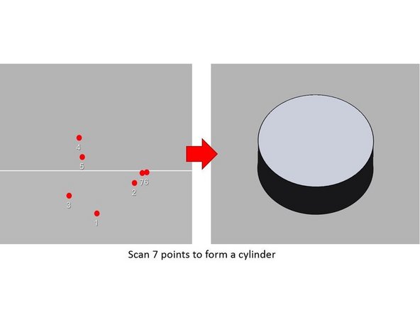
Cylinders => Scan 7 points to form a cylinder surface
-
Cones => Scan 8 points to form a cone surface
-
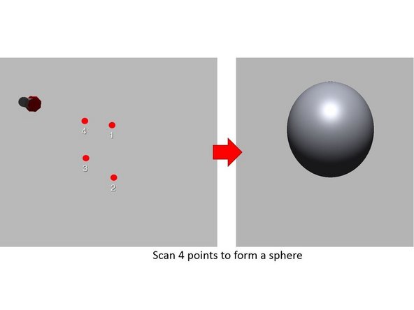
Spheres => Scan 4 points to form a sphere surface
-
Tori => Scan 8 points to form a tori surface
-
-
-
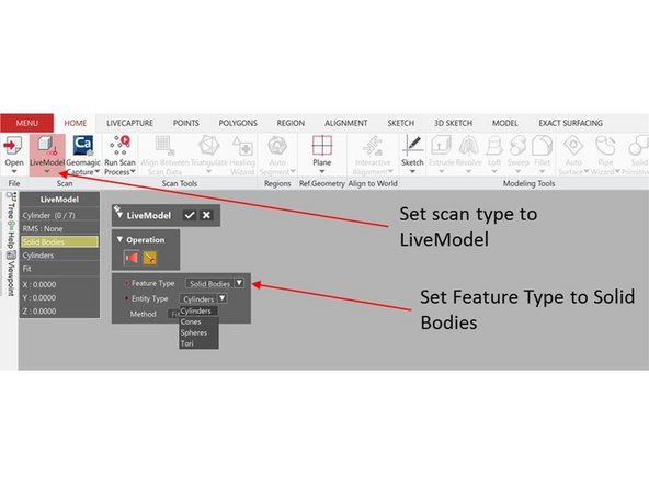
Set the scan mode as LiveModel
-
Set Feature Type as Solid Bodies
-
Four types of solid bodies can be created:
-
Cylinders => Scan 7 points to form a cylinder
-
Cones => Scan 8 points to form a cone surface
-
Spheres => Scan 4 points to form a cylinder
-
Tori => Scan 8 points to form a tori surface
-
-
-
Set the scan mode as LiveModel
-
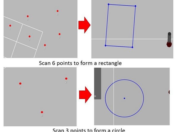
Set Feature Type as Sketches
-
Five types of sketches can be created:
-
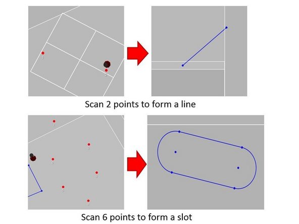
Lines => Scan 2 points to form a line
-
Rectangles => Scan 6 points to form a rectangle
-
Circles => Scan 3 points to form a circle
-
Points => Scan 3 points to generate a point at the center of those 3 points
-
Slots => Scan 6 points to form a slot
-
-
-
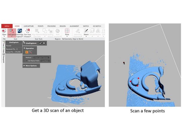
The probe can be run in combination with the 3D scanner
-
1st, use the scanner to get a 3D scan of the object
-
2nd, switch to the probing mode and scan a few points
-
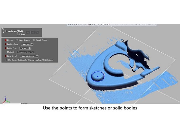
Use the scanned points to form sketches or solid bodies
-
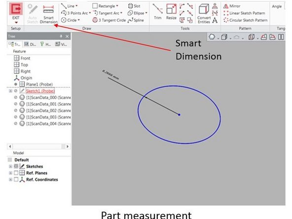
Use smart dimension to perform part measurement
-


Congratulation you have learn the basic skill needed to operate the probe in Romer Absolute Arms
Congratulation you have learn the basic skill needed to operate the probe in Romer Absolute Arms
Cancel: I did not complete this guide.
One other person completed this guide.