Introduction
Parts designed for practical use typically require small gaps, called clearances, to accommodate uncertainty in the manufacturing method, called tolerances. For example, a shaft designed to slide in a socket needs to be slightly smaller than the hole to fit without excessive friction. This guide reviews best practices for creating clearances with a particular focus on 3D printing.
-
-
Any manufacturing process contains inherent uncertainty in the toolpath and interaction between the tools and work piece
-
This uncertainty translates into variance in the dimensions of the manufactured part
-
This uncertainty is called the tolerance
-
In the example shaft and hole the completely opaque colors represent the designed dimensions and the translucent shapes represent the tolerance dimensions
-
As evident from the image, designing the shaft to exactly the size of the hole would result in the manufactured sizes overlapping. The real parts would not fit together.
-
The gap between the designed dimensions describes the clearance
-
-
-
Additive manufacturing (AM), or 3D printing, carries unique sources of uncertainty in built dimenisons
-
Most methods of AM build parts layer by layer, so tolerances typically differ between the z axis and xy plane
-
In the z axis, uncertainty in the layer height defines the tolerance
-
Tolerances in the xy plane stem from more sources of uncertainty, including material flow rate and tool position
-
Typically the Z axis tolerance is larger, and used to define the clearance
-
-
-
Clearances account for tolerances when designing parts that fit together
-
The clearance between two parts defines the nature of the fit:
-
A small clearance yield might a friction fit where the parts lock together
-
A large clearance allows the parts to slide past each other easily
-
-
-
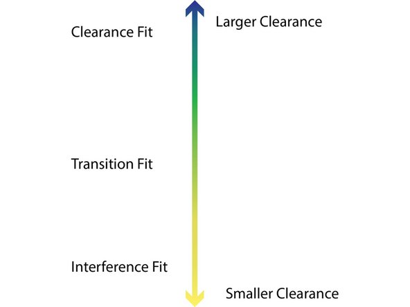
The size of the clearance depends on the desired fit
-
Clearance fits allow the parts to slide or rotate freely. In these fits, the clearance leaves extra space between the tolerances.
-
With transition fits friction holds the parts in place, but disassembly is still possible. In a transition fit, the clearance roughly equals the tolerance.
-
In an interference fit, friction completely holds the parts from sliding or rotating. Interference fits typically hold assembled parts together semi-permanently. In an interference fit, the clearance is smaller than the tolerance.
-
-
-
Identify the desired fit for the application. This determines if your clearance equals, exceeds, or is smaller than the tolerance.
-
Identify the tolerance of the manufacturing process.
-
When creating parts with AM, approximate the tolerance for each part as equal to the layer height
-
For a fit involving two parts, remember to double the tolerance zone.
-
For example, to create a transition fit between two parts made with an FFF/FDM printer at a layer height of .1 mm:
-
Approximate the tolerance of each part as +/- .1 mm for a total tolerance zone of +/- .2 mm
-
Reduce the dimensions of one part involved in the fit by .2 mm to create a clearance equal to the tolerance
-
-
-
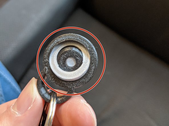
When rapid prototyping options are available, test clearances and tolerances by fabricating sample parts with the desired fit
-
For example, the part in this image tests a clearance fit. The rings should rotate freely if the tolerance was estimated properly.
-
If possible, fabricate a simple two-part fit with several copies, each containing a range of clearances. This enables an accurate estimate of the tolerance inherent to the manufacturing process.
-