Introduction
This is a basic introduction to using WAM to prep files for cutting. This assumes you already have a .dxf or a .svg file to be cut.
-
-
The Wazer uses an online software called Wam to prep files to be cut. It includes all the preset settings for different material types and thicknesses, so there is little to no guesswork
-
Go to wam.wazer.com
-
Username: RapidProtoLab
-
Password: WaterJet28
-
Wam only supports .dxf or .svg files
-
-
-
To change the import units of the file, select the gear icon in the top left, then select millimeters or inches
-
If you want to clear the cutting bed, click the "W" icon in the top left
-
To import a file, click "import file", select the file you want to import, and click "open" or press enter
-
You can increase the number of copies of the part by clicking the "+" icon
-
If your lines are not constrained by an outer boundary, split will allow you to move individual vector lines. This can be useful if you have many individual parts in one file
-
-
-
Select "Scale and Position" on the left
-
To reposition the file, you can either drag the model to a part of the bed you want to cut on, or select the X and Y coordinates
-
You can also scale the model, either collectively or just X or Y
-
-
-
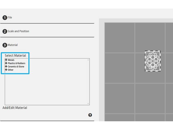
Click "Material" on the left to get to the material menu
-
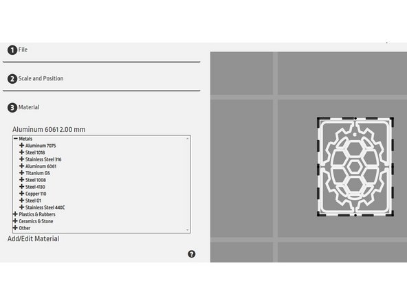
The materials are grouped by type of material. They are NOT in alphabetical order
-
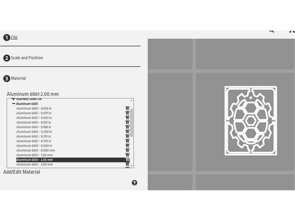
Select the "+" for your category, then select your material, and final choose the settings for your thickness. This can be in inches or millimeters, regardless if your model units
-
If your thickness is not listed, use the settings that are the next thickest to ensure the cut goes all the way through. NEVER use settings that are thinner than your material
-
-
-
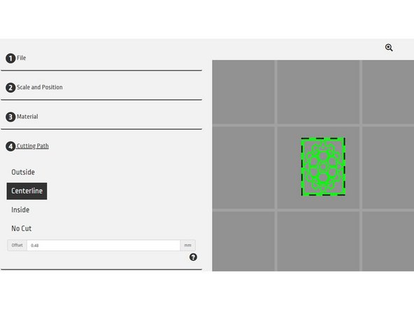
Next you will select which part of the lines you want to cut on.
-
Select the model(s) you'd like to cut. The white is your model boundary, and the green is the cutting path with the offset due to the width of the water
-
Outside will cut the outside of your model. For outer perimeters, this is the outside of the lines, but for inside cuts, it will cut the inner part of the lines. This will give you dimensionally accurate parts
-
Centerline will cut the center of your lines
-
Inside will cut the inside of the model.
-
No cut will not cut out your part
-
You can select different cutting paths for different models on the build plate if you'd like
-
-
-
If you get a warning that says "Offset size will remove some geometry", this means a feature of your model is too small to be cut as is
-
The offset is .48mm because this gives the right distance away from the center of the cut lines to have dimensionally accurate parts
-
You can edit this if you want the cuts to be tighter to the model, but keep in mind this will not change the width of the water
-
It is usually best to leave the offset as is for engineering parts, and edit the model to have large features
-
-
-
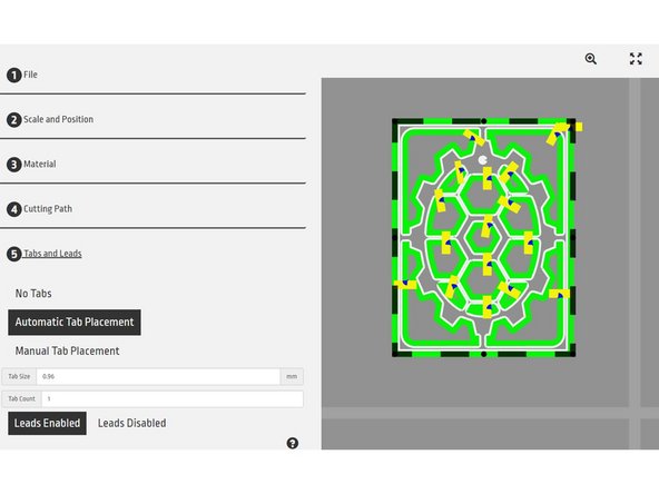
Tabs help keep a part in place while cutting, preventing pop-ups which would result in a failed cut and potentially time-intensive maintenance
-
You can choose to automatically place tabs on all cut parts, or manually move them by dragging the yellow rectangles to the part of the line you want the tab on
-
You can also change the size and number of tabs if your part is large
-
Leads help create a cleaner cut and should always be left on
-
-
-
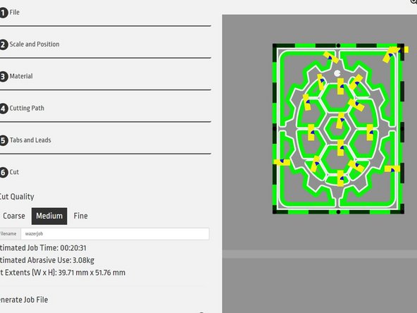
Select "cut" on the left
-
Select the cut quality you'd like
-
Coarse will go faster but will be much more rough, especially on the back side. Fine will make a much cleaner cut but will take longer and use more garnet
-
Name the file and click "Generate Job File". This will download the gcode to your computer. The file name can be no longer than 13 characters
-
Transfer the file to the SD card, found on the right side of the Wazer
-
-
-
You've now prepared your file to be cut! Next you'll actually go to the Wazer and cut your file
-
Cancel: I did not complete this guide.
11 other people completed this guide.


