
-
-
To perform a full-body scan, the person who will get scanned needs to be position in such a way so that there is at least 1 meter distance around him
-
You start by scanning the feet and gradually move up while rotating around the person as shown in the First Figure. You will move like a spiral from bottom to top
-
Some scanning tips:
-
It is recommended to first finish scanning the feet, then move to scan the body, and finally move to scan the head.
-
Although you can go back to scan the feet after finish scanning the head, there is a possibility that the person may have moved slightly during that time that can causes misalignment
-
You may need to use a leader as shown in the second figure to scan the top part of the head
-
You need to finish the scan at once. One the person move it will be almost impossible to align the scan
-
-
-
You should get a scan as shown in the first figure. Checked to make sure that you have scanned all/most of the body. The area with missing scan are shown in red color as shown in the first figure
-
You need to finish the scan at once. One the person move it will be almost impossible to align the scan
-
When finished, import the scan file into a micro SD card so that it can be opened with Artec Studio (Please refer to the beginner tutorial for more detail about the process)
-
Run the Artec Studio software at the scanner PC. Import the scan result using the import feature as shown in the third figure
-
-
-
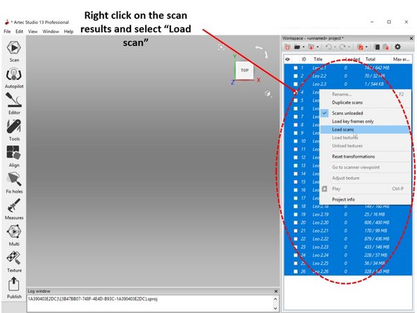
Most likely you will end up with multiple scan data which is listed in the right window
-
To load the scan results, right-click on the scan results and select Load scan as shown in the first figure
-
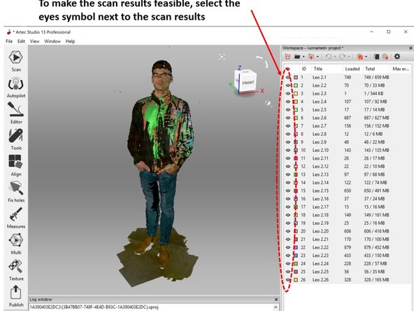
To make the scan results feasible, select the eyes symbol next to the scan results as shown in the second figure
-
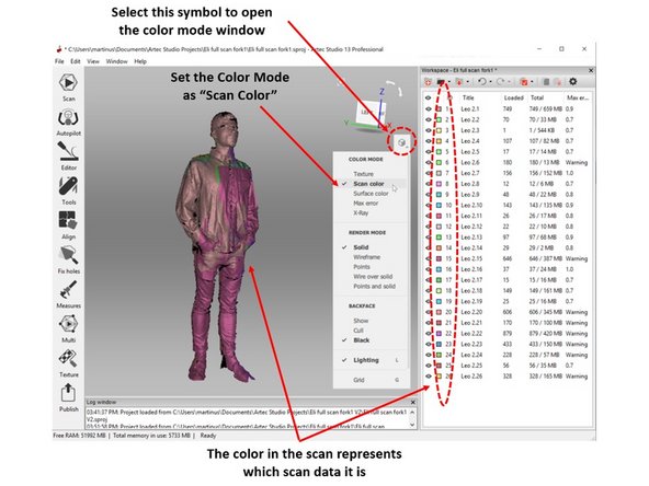
To open the color mode window select the cube symbol next to the coordinate system as shown in the third figure
-
Set the Color Mode as Scan Color
-
The color in the scan will be set to match the color code of each individual scan as shown in the third figure
-
-
-
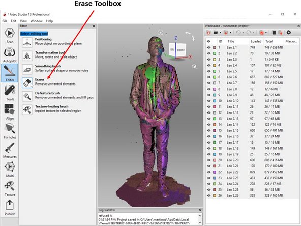
The next step is for base removal by using the Erase toolbox under Editor as shown in the first figure
-
Highlight area you want to remove by using Ctrl + Left Mouse Button (See the second figure)
-
Select Erase to erase the highlighted area
-
For undo, press Ctr + z
-
At the end of this step, you should get a result as shown in the third figure
-
-
-
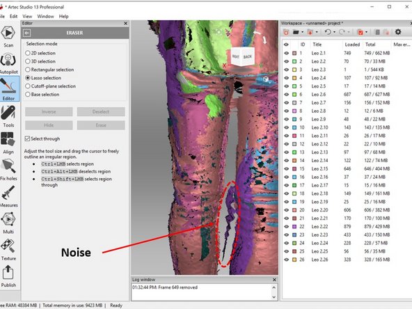
Perform all around check on the scan result for noise as shown in the first figure
-
Once you identify a noise, you need to track which scan data this noise belonges
-
This can be done by matching the color of the scan with the color designation of each scan which is listed on the right window
-
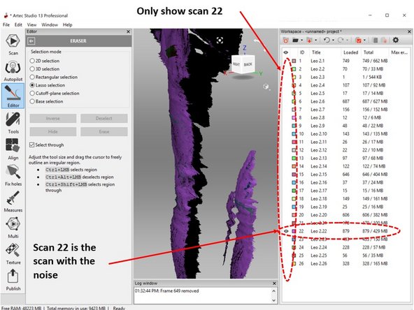
You can double-check by only showing one scan at a time as shown in the second figure
-
In order to avoid removing other scan data, when removing the noise, show only the scan data with the noise as shown in the second figure
-
-
-
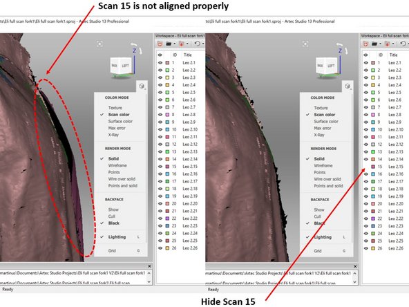
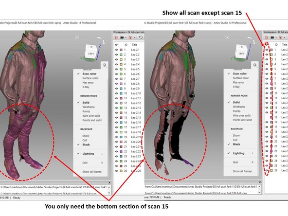
Check if you have any scan result which is not well aligned as shown in the first figure
-
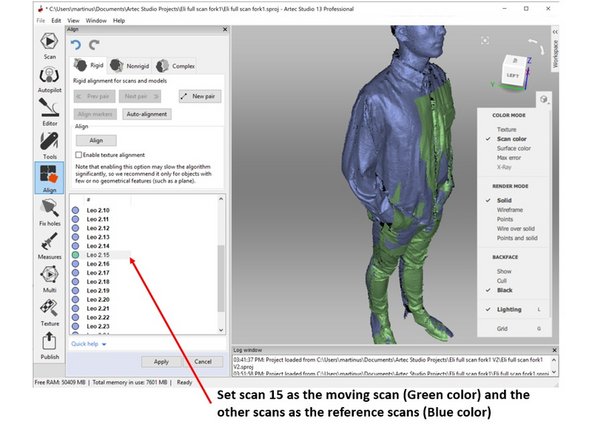
If yes, run the alignment toolbox as shown in the second figure
-
Set the scan you want to realign (scan 15) as the moving scan (Green color) and the other scans as the reference scans (Blue color) as shown in the second figure
-
Select New pair to add align Marker between the 2-scan data as shown in the third figure
-
5 to 6 points are sufficient
-
To start the alignment process select Align
-
When finished select Apply at the bottom window
-
-
-
You may found a case where it is impossible to fix the alignment
-
This most likely because of the person is moving which causing a portion of the scan no longer align
-
For this case you can try to see if you can remove the portion of the scan data which is not-align
-
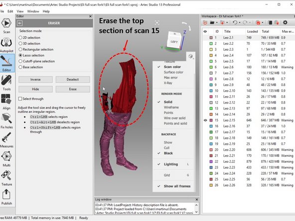
For example, for the case shown in the first figure, you can conclude that only the bottom section of scan 15 is needed. The top portion which is not align is actually not-needed
-
Therefore, you can remove the top section of scan 15
-
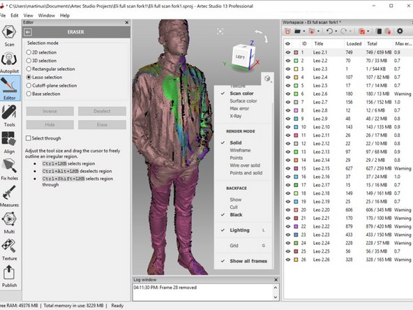
The third figure shows how the scan look like after the top part of scan 15 was removed
-
-
-
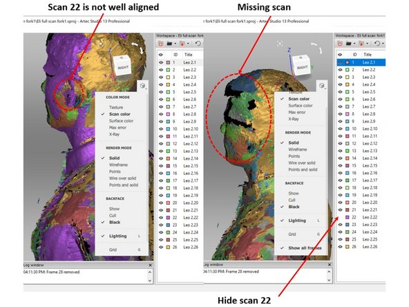
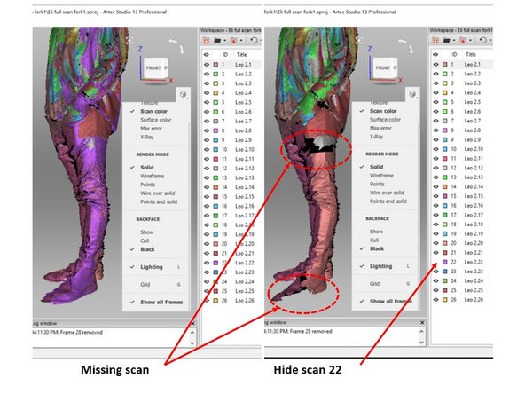
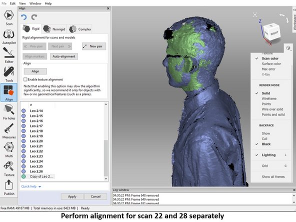
You may encounter a case where it is not possible to delete the non-align scan as it will cause missing scan
-
For example, in the case shown in the first figure, scan 22 is not well aligned in the ear section. However, you cannot remove the scan as this will cause a missing scan
-
Moreover, if you check the bottom part of the scan (As shown in the second figure), you will see that the bottom part also cannot be removed as it will cause missing scan
-
For this case, it is not possible to just remove a portion of the scan as done previously
-
To mitigate this problem, you will need to separate the top and bottom sections
-
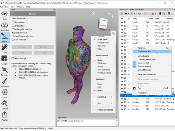
This can be done by first making a copy of the scan as shown in the third figure
-
-
-
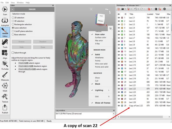
You should have a copy of the scan data (Scan 28 is a copy of scan 22) as shown in the first figure
-
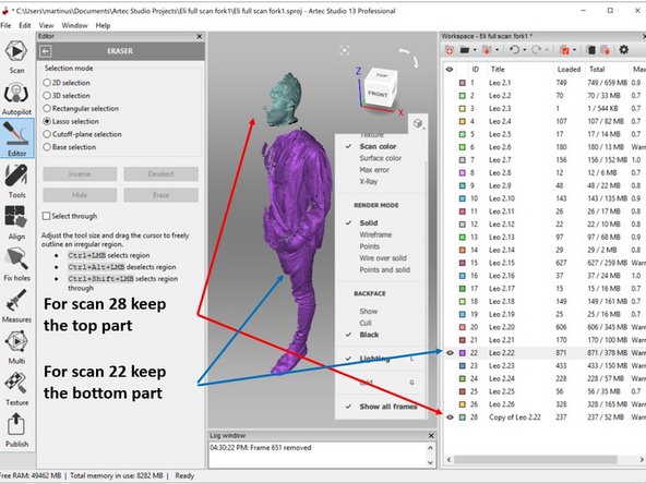
Use erase feature to remove the top part (Keeping the bottom part) for the scan 22 (The original scan data) as shown in the second figure
-
Use erase feature to remove the bottom part (Keeping the top part) for the scan 28 (The copy of scan 22) as shown in the second figure
-
Perform alignment for both scans (Scan 22 and 28) separately as shown in the third figure
-
-
-
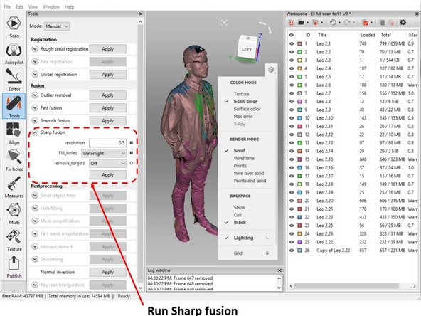
When you feel that you have a good alignment for all of the scan data and there are no noticeable noise, run the sharp fusion as shown in the first figure
-
You can use the default setting for the sharp fusion.
-
Make sure that the watertight is selected under Fill holes
-
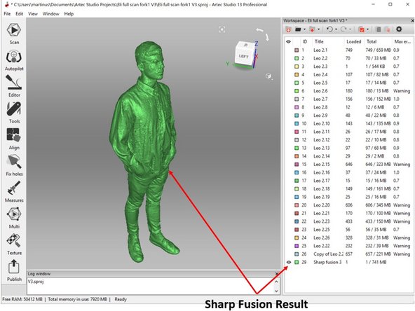
You should get a watertight result as shown in the second figure
-
-
-
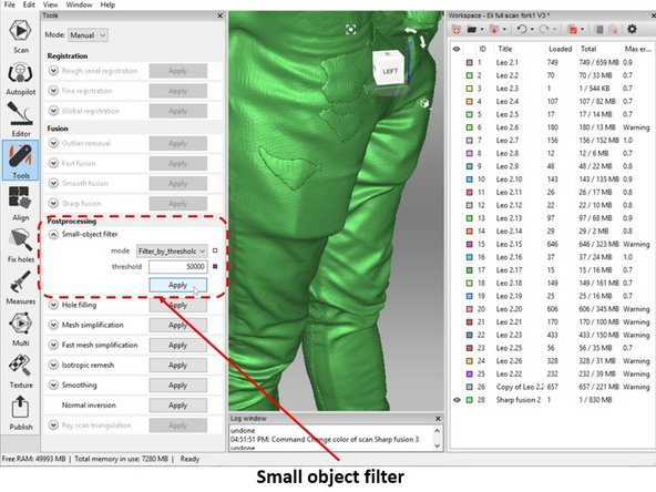
Analyze the combine scan result, check if there are small clusters of objects (Noises) as shown in the first figure
-
The noises can be removed by using small object filter feature as shown in the second figure
-
Adjust the threshold to determine the upper limit of the size of the small object to be removed. You can increase the threshold if it is not sufficient to remove all of the small objects
-
The third figure shows how the scan will look like after small object filtering
-
-
-
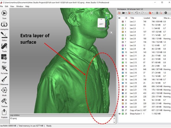
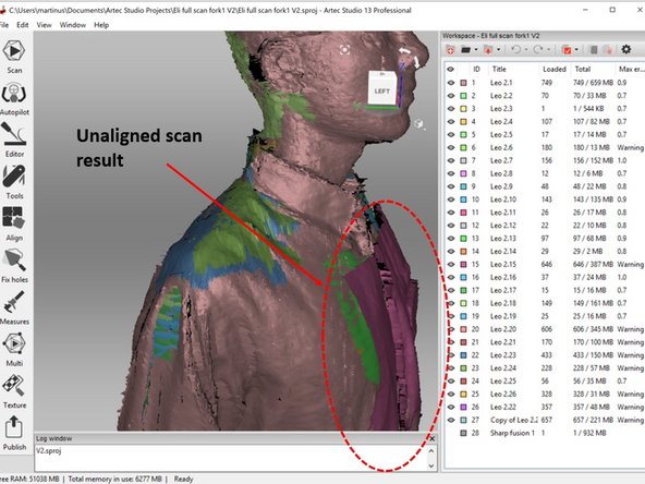
You may find a case where you see that there is an extra layer of the surface as shown in the first figure
-
This is most likely caused due to the unaligned scan result as shown in the second figure
-
This can be fixed by running scan result alignment as explain in step 6 - 9 and rerun the Fusion
-
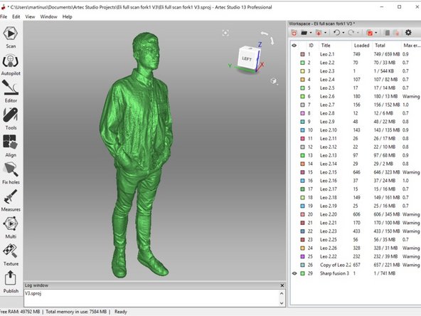
At the end of this step, you should get a clean scan data as shown in the third figure
-
-
-
Artec studio record the color texture of the scanned object
-
The original color of the scanned object can be added into the mesh by using Texture feature
-
Go to Texture, highlight all of the scan data from the left box, and hit apply
-


Congratulation you have learn sufficient skill to perform full body scan using Artec Leo
Congratulation you have learn sufficient skill to perform full body scan using Artec Leo
Cancel: I did not complete this guide.
One other person completed this guide.
One Comment
Guide is useful, however we should maybe split all of the subskills into their own guides These tools seem widely applicable to all post processing.
Evan Hutzell - Resolved on Release Reply