Introduction
This is a step by step guide to go from a customer provided STL file to a FAB3 File that is ready to be printed on the ProX 200. Throughout the process it is important to note the special considerations that must be made for metal 3D printing. See the 3DSystems Direct Metal Printing guide for a great introduction and some background.
-
-
First ensure that you are logged into the correct user (.\prox) on the computer labeled "ENGRWKEGR0126B".
-
To launch the software, either select the "3D Icon" on the task bar or start menu, or search DMP ProX Manufacturing in the start menu.
-
On startup, select the ProX 200 printer in the "Choose your machine" interface.
-
Next, select the correct material (at the time of writing it is LaserForm Ni625 (Specific Fused Silica Lens Base)
-
-
-
Click the button with a cube and green plus sign to begin the part import process.
-
Select the correct .stl file. (this software can only take STL files)
-
Select the correct family - with the Inconel profile this will be Part - Hexagonal Sintering
-
Once this is done, click next to go to the orientation page.
-
-
-
Before starting on the orientation and supporting portion of the process, validate that the part is scaled correctly and fits within the bounds of the build plate.
-
The build volume of the ProX is 140 x 140 x 100 mm (5.51 x 5.51 x 3.94in) for reference.
-
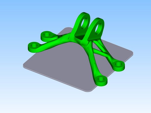
To check this, click next at the bottom of the screen and then import to see how the part would look like if it was placed on the build plate.
-
If the part is clearly too large or too small, it will either need to be modified if it is a design problem, or can be resized in a mesh-editing software like meshmixer.
-
-
-
Repeat step 2 to get back to the orientation window.
-
Here you can click and drag on the part to orient it. Alternatively use the keyboard to rotate the part or manually adjust the angles on the left hand side menu.
-
There are a couple of options available that allow you to lock rotation to only one axis that might be useful in some situations.
-
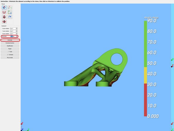
Set the elevation to 4mm.
-
To confirm an orientation, click the "Orientate" button on the left.
-
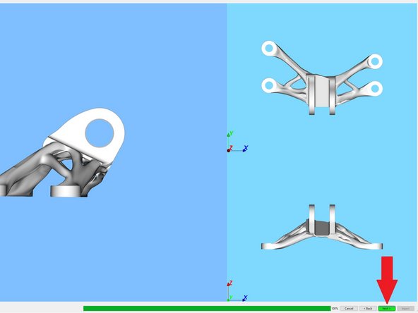
Click next to go on to the supporting step.
-
Warning: It may feel like you are rotating the view when you click and drag on the part, however you are actually rotating the part.
-
-
-
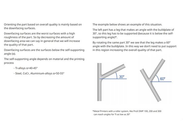
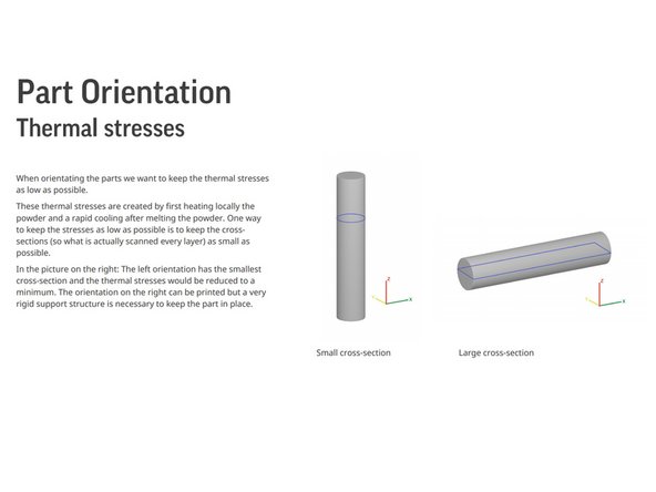
To better understand how to orient parts optimally, ready this document: 3DSystems DirectMetalPrinting Guide
-
-
-
Supporting the part is the most complicated part of slicing for the ProX and must be done carefully to ensure the part comes out well.
-
It is also important to take care to not add to many supports as they are difficult to remove.
-
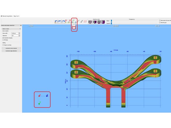
It might be useful to orient the view to see the part from the bottom. Select the Y-X plane and the Z- direction in the top menu.
-
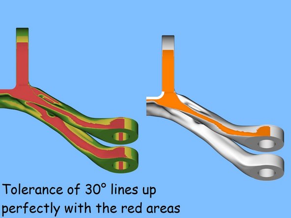
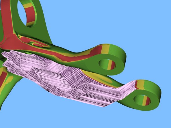
Areas colored red will need to be supported (30 degrees from the horizontal or lower).
-
Do supports in separate individual steps if you suspect support deformation is necessary.
-
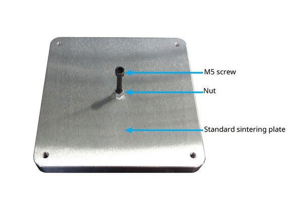
Portions that are the lowest point of the part (i.e. touching the build plate) still need to be supported as the support acts a spacer between the part and build plate in the 4mm gap between them.
-
-
-
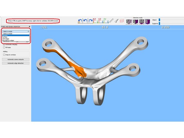
Painting mode is useful for creating supports on complex surfaces.
-
To use painting mode select 'painting' from the <select a mode> drop down on the left.
-
Ctrl click to begin painting a zone.
-
Zones will be the areas that get supported.
-
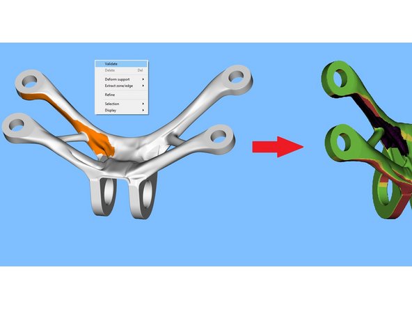
Once you are satisfied with your zone, right click and click validate.
-
-
-
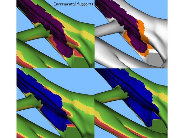
Since the shading of the part disappears when going into the zone creation modes, you need to use an incremental approach to adding supports.
-
If the zones are touching, they will automatically be merged into one.
-
Ctrl-z does work in the support window but may need to be done multiple times if combining zones.
-
Adjust zone width to make grabbing larger or smaller areas easier
-
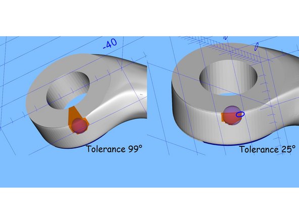
Tolerance affects how surface gradation is handled
-
-
-
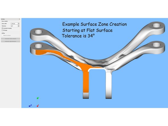
Surface mode is good if you have one large flat area that doesn't have much variation.
-
The surface tools works by selecting all surfaces that are at most <tolerance> degrees away from the surface you left clicked.
-
This can give some very predictable behavior if you click on a surface parallel to the horizontal X-Y plane. If you set the angle to 30 degrees you will select every face that is 30 degrees from the horizontal plane or lower.
-
Hold ctrl and left click on different surfaces to select multiple surfaces.
-
-
-
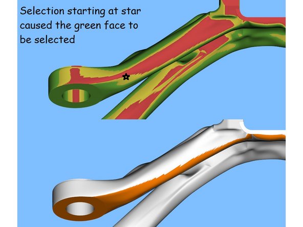
Clicking on surfaces that are not parallel to the horizontal as a starting point with high tolerance may lead to poor selections.
-
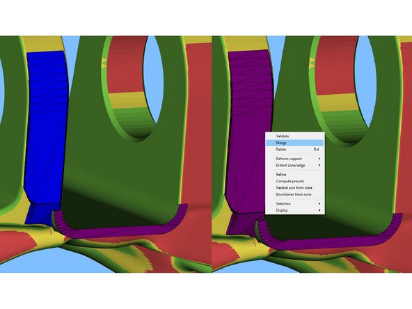
If you want, you can merge zones into one at any point even if they are not touching by left clicking both to turn them purple and then right clicking one and selecting 'merge'. This can be convenient in some situations.
-
-
-
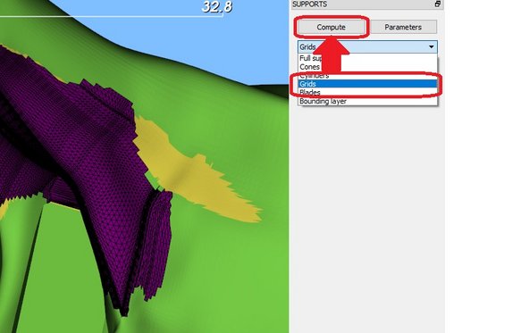
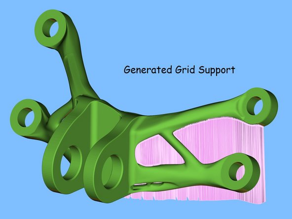
To complete your support, select the zone of interest so it turns purple.
-
Select Grid support from the drop down menu on the right (this is the type of support that we use all the time)
-
Click Compute.
-
Wait for the support to be generated. If this is taking too long or the software freezes, consider making the zone smaller.
-
-
-
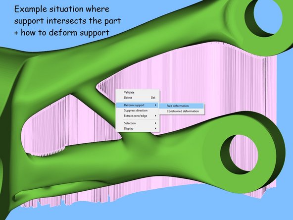
In situations where the surface quality needs to be maximized or support would be difficult to remove due to it touching another portion of the part, support deformation may be employed to move the support out of the way.
-
Select a support (it becomes brighter), right click it, mouse over 'Deform support' and select 'Free deformation'
-
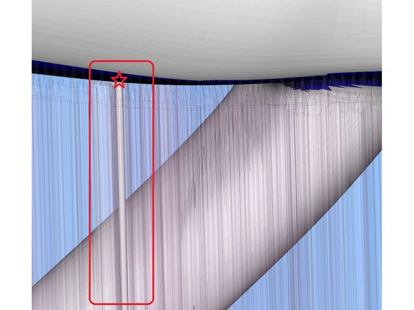
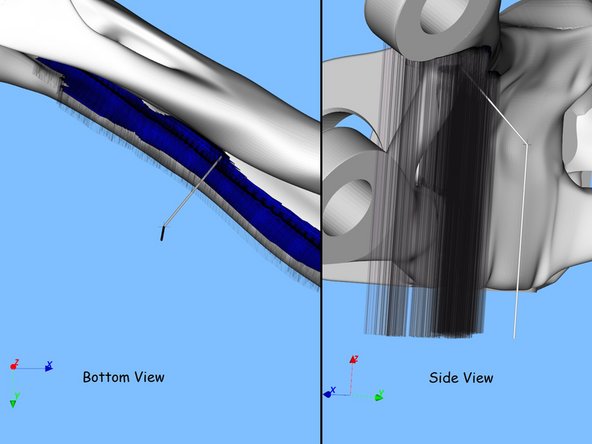
Once in deformation mode, the support will become transparent and a thin grey column will appear at some point in the midst of the support.
-
Mouse over near the top of the column until the mouse changes from a pointer to a hand.
-
Grab the top of the column and move it in some direction away from the part if it is hidden.
-
-
-
The way that you move this cross-hair will affect how the support is deformed.
-
To guess what will happen when you validate the deformation, imagine it as if every vertical support line will follow the same trajectory as the column shows.
-
Generally you would want to move the crosshair so that it is above flat ground and not above the part.
-
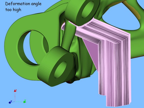
Do not move the crosshair vertically too much as you want to minimize the amount of angled support.
-
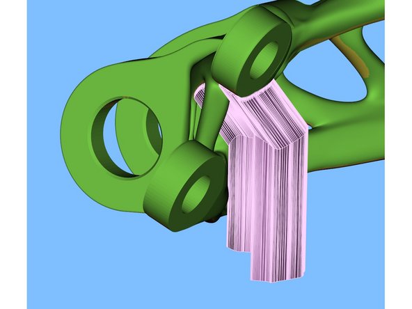
Do not move the crosshair too far horizontally as that may result in unstable support. One way to notice this is if fins appear under the supports.
-
-
-
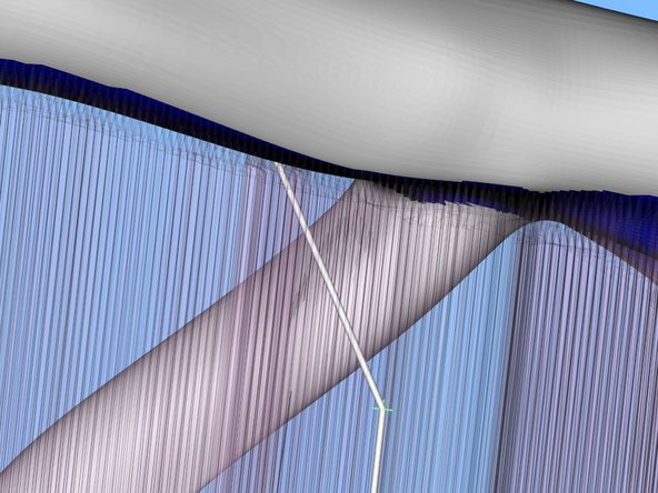
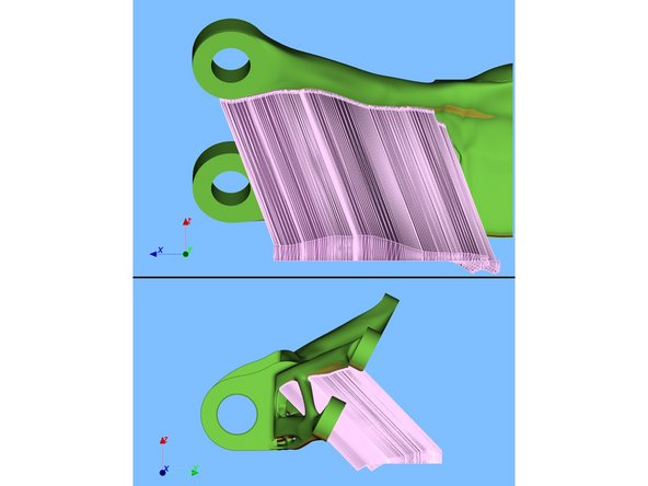
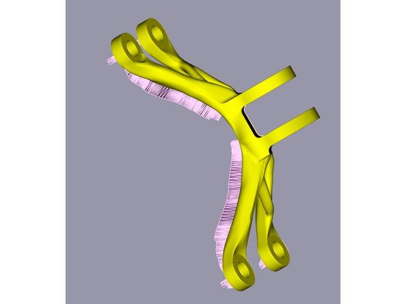
Example of a good deformed support
-
Does not intersect part, no fins, no overhangs.
-
If deforming an entire support is problematic, break it into sub-sections by building the support in several steps.
-
-
-
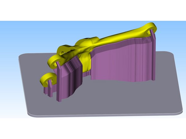
This is an example of a fully supported part.
-
Once you are ready for the next step, click import on the bottom right.
-
-
-
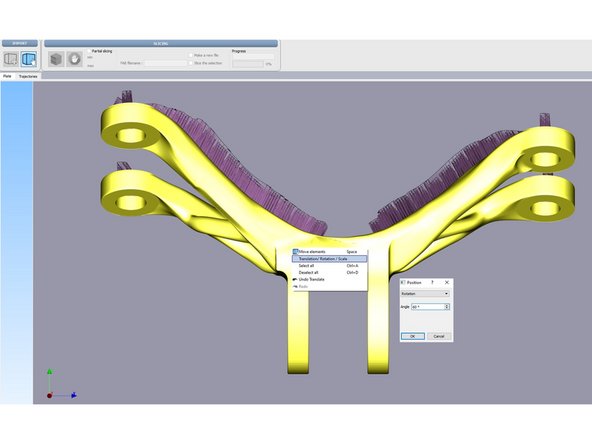
Select the Cube with a hand in the top left to enter support mode.
-
Select the part by left clicking on it. Right click on the part. Select Translation Rotation Scale.
-
Select Rotation from drop down menu and set the angle to an appropriate amount.
-
The goal is to orient the part in such a way that the roller would not catch on a flat face (on approach, it comes onto only a small portion of the part like a corner)
-
See the third picture for an example of an orientation of the part that would not result in the roller catching on it.
-
-
-
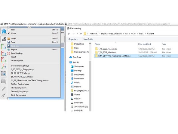
Before proceeding to slicing (which may crash), please save the part by clicking the home icon and then save as. This will save a physx file - the file that describes the model with supports and location on the build plate.
-
Navigate to \\engrfs214v.ad.umd.edu\tw\0126\ProX\Current
-
Create a new folder with the format as shown (MM_DD_YYYY_FirstName_LastName)
-
Enter the folder, name the file with a descriptive name (what is the print?) and hit save.
-
Copy the filepath for this folder so that you can use it in the next step.
-
-
-
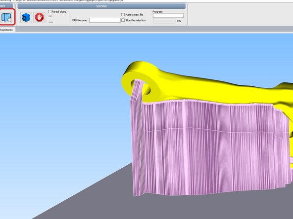
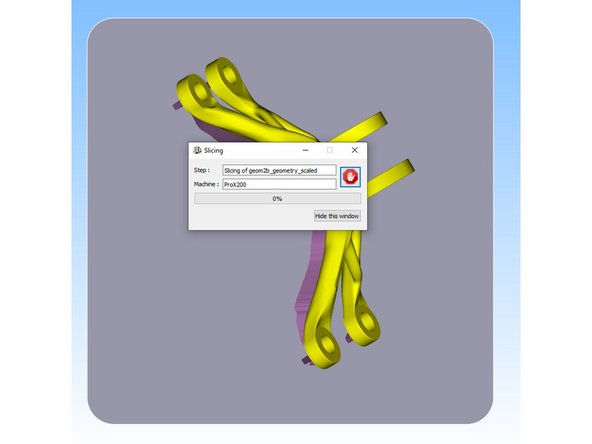
To run the slicing process, click the blue stack in the top panel on the left.
-
You will be prompted to save the part (this time as a FAB3 file), use the address you copied in step 17 to get to the right folder quickly.
-