Introduction
Slicing is required to take 3D design files and send them to the printer before printing. Good slicing will lead to an easier and more efficient print process, but poor slicing can lead to failed parts.
Images by: Terrapin Works
-
-
Install the latest version of Fabricate onto a powerful computer
-
Fabricate uses significant CPU, GPU and RAM resources
-
20-30 part builds have used 100% of a GTX 1080ti and over 16 GB of RAM
-
Files brought into the software can be in many different formats, but .stl, .3mf, and .obj are the most common
-
Parts intended to be printed successfully should follow all parameters of the design guide for the shop system
-
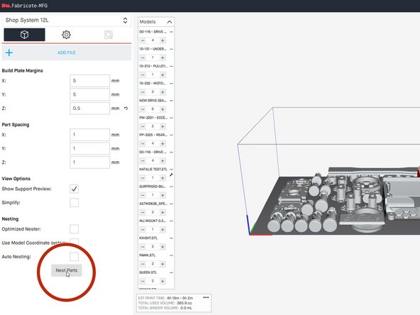
PLEASE NOTE. These images show the print volume to be 12L. The actual print volume is 8L. Make sure this setting is correct before slicing.
-
-
-
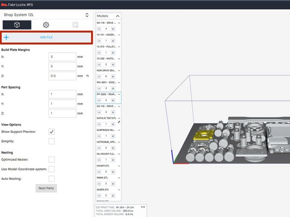
Set the XYZ Build Plate margins as shown
-
0.5mm Z margin is selected to introduce a fresh layer of powder before the model prints
-
Set the Part Spacing options as shown
-
XY spacing must be set to 5mm to reduce pitting from parts being too close to each other
-
Z spacing can be small because floors and ceilings do not disturb the powder after just a few layers
-
Turn off Auto Nesting, this option when selected adds time by re-nesting each time a part is added
-
-
-
Click add files or drag and drop files into the build area
-
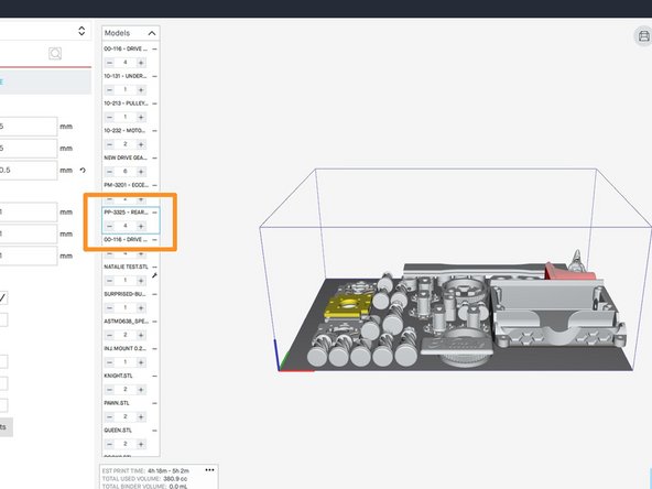
Change quantity in the left sidebar
-
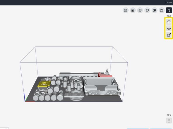
Translation and rotation are found on the right side
-
Scale and units can be changed with the scale button on the right
-
-
-
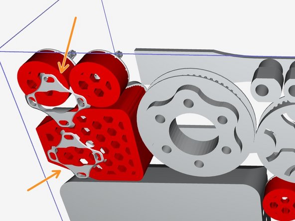
Parts with overhanging geometry when sintering will need part setters
-
Parts must be put into the build area in the same orientation as sintering in order to generate setters properly
-
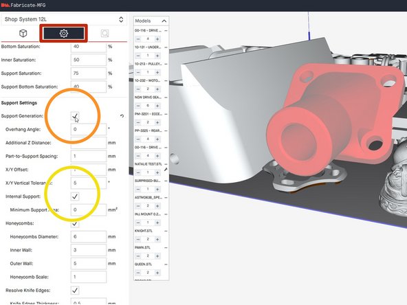
Click on the part(s) that require generated setters
-
Select the Parameter Settings button
-
Scroll down and select the Support Generation option
-
If desired, unselect the internal support options
-
Internal supports can be quite difficult to remove
-
-
-
Click the Nest Parts button in order to arrange parts
-
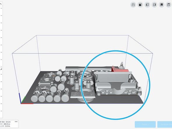
To influence where parts are placed, put them outside of the build area on the side closest to where they are desired
-
In order to get a "fresh" nest, all parts can be moved outside of the build area and then re-nested
-
If setters were generated, it is possible that parts are clipping through the generated setters
-
Manually move these parts away from the setters until they appear to be visually spaced away from all print areas
-
Large parts should be printed on the far right of the build plate as much as possible due to the direction of the powder spread roller
-
-
-
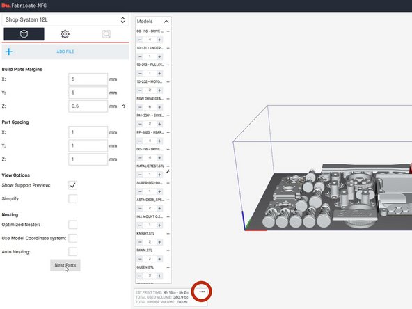
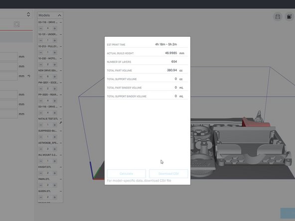
Optimize the nesting as much as possible to reduce build height
-
Check build height by clicking on the 3 dots in the bottom left area
-
Every mm of print height will require loading approximately 1.25 kg of powder at a spread ratio of 2.1
-
-
-
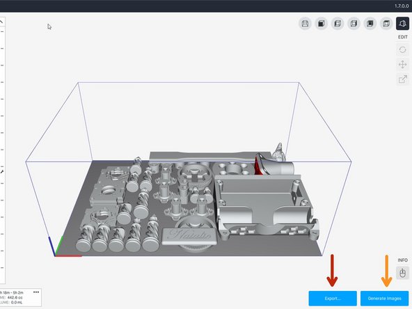
Export a .3mf of the full build without setters
-
This file can be used to edit the build in the future if necessary
-
This option can also be used to save builds that are in progress of being sliced and need to be worked on later
-
This step may take 15-20 minutes depending on complexity and quantity of parts
-
Generate Images and save locally
-
This file is copied to the printer and is used to print the job
-
This step may take 20-30 minutes depending on complexity and quantity of parts
-
Copy files to the flash drive to be transferred to the printer
-