-
-
In general, CAD software uses the following process to create 3D solids: create a sketch then manipulate that sketch into a solid body
-
This guide provides an overview of some of the more common tools for turning sketches into solid bodies
-
The figure in the red box is an example of a sketch. To learn more about creating sketches, refer to Introduction to Sketches in Fusion 360
-
-
-
An extrusion essentially pulls a 2D profile into a 3D body where all cross sections in the direction of the extrusion match the original profile.
-
The extrusion tool icon is found in the "Create" section of the Toolbar
-
Creating an extrusion requires a closed profile.
-
Specify the height of the extrusion. Extrusions with negative heights can cut through other solid bodies.
-
-
-
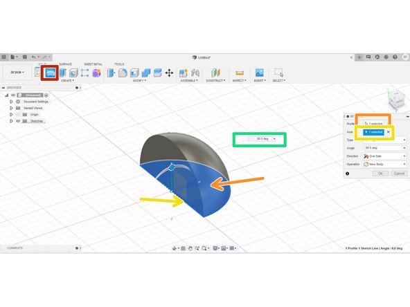
The revolve tool creates a 3D body by rotating a closed profile about an axis.
-
The icon for the revolve tool is found in the "Create" section of the tool bar
-
The revolve tool requires a closed profile, so first we select the closed section of the sketch.
-
In this example, we selected the line in the semicircle as the axis about which to revolve.
-
After selecting the profile and axis, we finish constraining the revolve by specifying the degrees of the rotation.
-
-
-
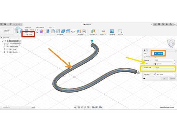
The pipe tool creates a solid by sweeping a basic shape through a specified path. The pipe tool is just a special type of a sweep; in a sweep tool rather than using a basic shape, the user creates a profile in a sketch.
-
Both the pipe and sweep tool are found in the drop down "Create" menu.
-
Using the pipe tool requires an open path from a sketch curve
-
The path tool also allows for the selection of shape used and specification of the shape's relevant dimensions.
-
-
-
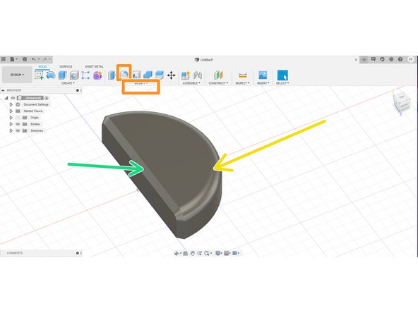
Fusion 360 provides several tools for modifying a solid body. Fillet and chamfer comprise two of the most commonly used tools for modifying solid bodies. They either smooth an edge into a curve or cut it into a slope respectively.
-
The figure indicated with a red box consists of an extruded semicircle.
-
The fillet tool is located in the Toolbar under the "Modify" section, while the chamfer tool is under the "Modify" drop down menu
-
The fillet tool, applied to the outer curved edge indicated with the yellow arrow, smoothed the edge into a curve.
-
The chamfer tool, applied to the top and side edges on the flat face indicated with the green arrow, cut the edge into a slope
-
-
-
This guide provides an explanation of some of the most commonly used tools for making solid bodies in Fusion 360.
-
This guide is by no means exhaustive, but it will give you a decent basis on which to start making your first designs
-
We recommend you practice these tools by trying to recreate objects around you in Fusion 360.
-
If you want some more practice, please head over to the Make a Planter in Fusion 360 guide for your first Fusion 360 project.
-
Cancel: I did not complete this guide.
One other person completed this guide.


