
-
-
Select the Material you would like to print in here. Make sure machine is set to "XiP."
-
If you are connected to the printer the material info will automatically update to what is loaded in the printer
-
Use the dropdown to match the Layer Thickness to the request
-
-
-
You can change the size of the part by scaling it from it's original size. Drag the green boxes to the desired size.
-
Nexa X displays a bounding box with the maximum exterior dimensions of the part.
-
You can also set an exact dimension for one of the dimensions of the bounding box.
-
Toggling the small lock will allow the axis to be scaled independently.
-
If a part exceeds the bounding box, an error will appear.
-
-
-
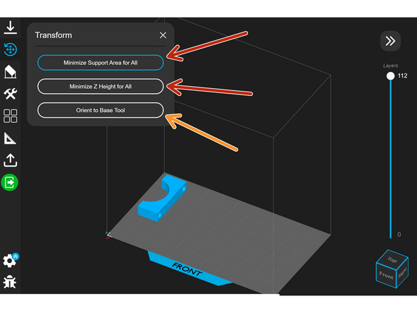
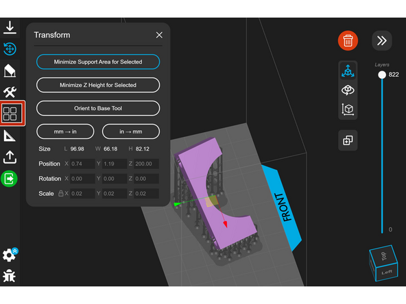
Some Nexa prints require support, and Nexa X optimizes the orientation for printing support.
-
To Auto-Orient, select "Minimize Support Area" or "Minimize Z Height." It is best to try both to see which orientation is better.
-
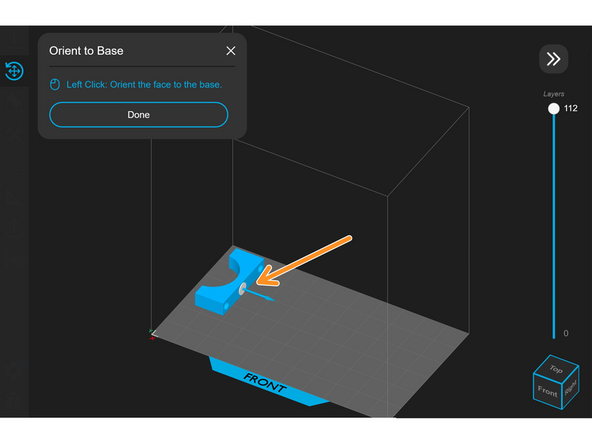
There is also the option, "Orient to Base Tool." This allows you to select a flat surface to place on the build plate.
-
Unlike the Form 3+, parts can be oriented with flat faces directly on the build plate. This is recommended because it will keep the part secure while it is printing
-
-
-
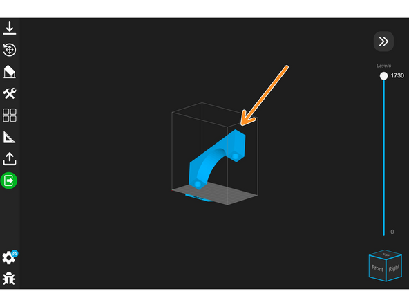
For some larger parts, the optimized orientation results in the bounding box extending outside the workspace.
-
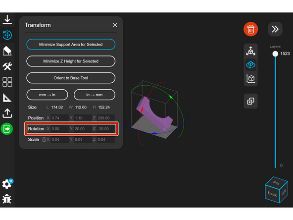
You are able to rotate parts about the X, Y, and Z axes of the bounding box using the circles surrounding them, allowing some larger parts to fit.
-
-
-
You can rotate the model an exact amount about the X, Y, and Z axes by typing a value where it says "Rotation."
-
-
-
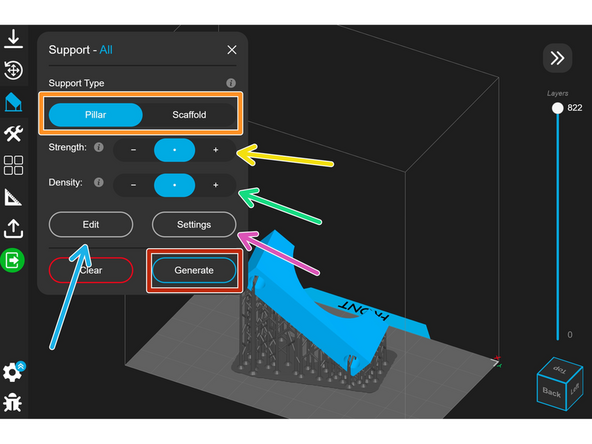
Click "Generate" to generate supports.
-
You can select between pillar and scaffold supports depending on the model you are printing.
-
The strength setting will increase the contact area of the supports with the model. This makes the support stronger, but may decrease surface quality.
-
Density increases the number of support structures. Also helpful for strength, but makes post-processing harder sometimes.
-
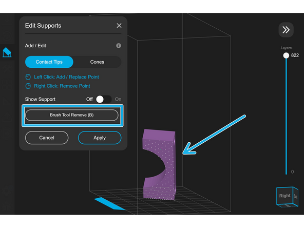
Supports can be manually added by clicking "Edit." Click the model to add support points and use the brush to remove points.
-
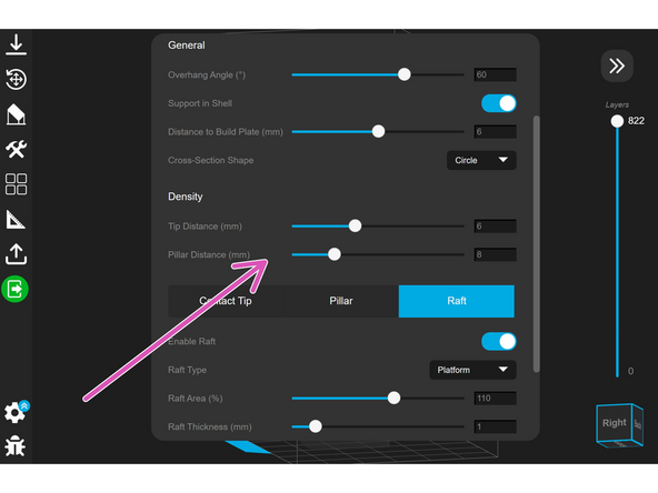
Additional settings can be found by clicking "Settings." This tab is generally not needed.
-
-
-
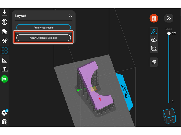
Selecting layout from the sidebar brings up options for nesting and arrays.
-
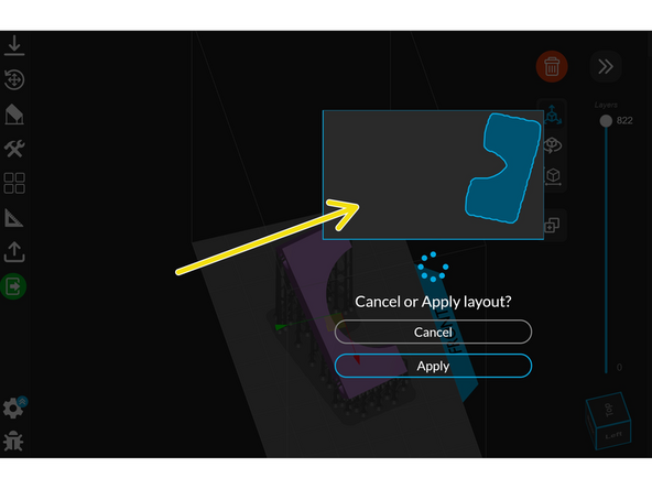
"Auto-Nest Models" orients all of the models on the build plate.
-
A preview of the model footprints will appear that you can choose to apply.
-
-
-
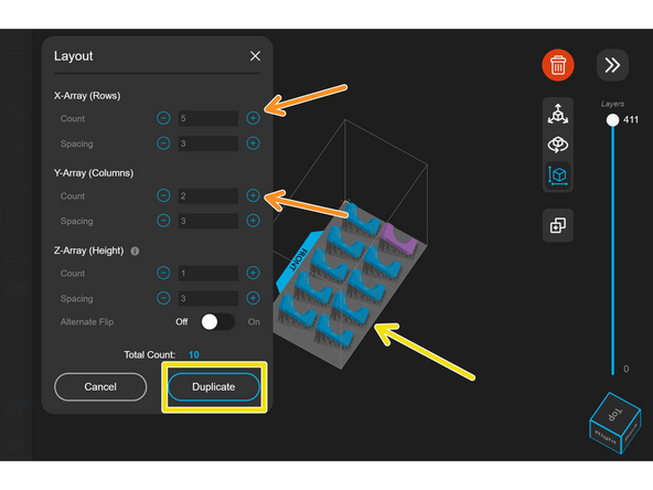
Selecting "Array Duplicate Model" allows you to print multiple copies of the same part.
-
Changing the count for the X and Y directions will add more copies to the build plate.
-
The copies are previewed in blue. Select duplicate to apply the changes.
-
It is recommended to complete this step after auto nesting the parts.
-
-
-
The job information required for quoting in Papercut can be found in the Details tab on the right side of the slicer.
-
-
-
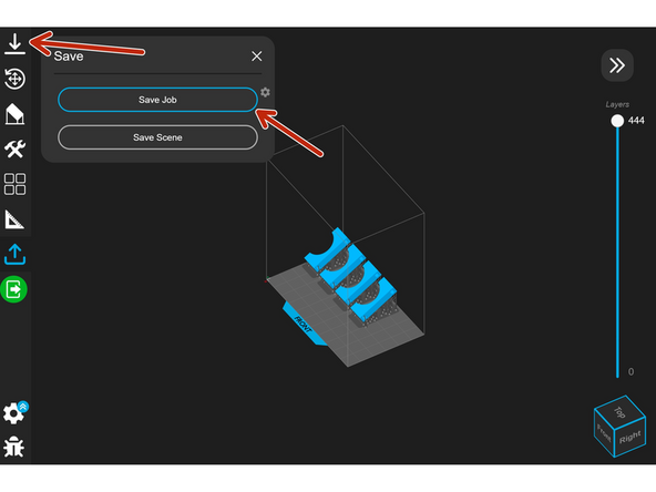
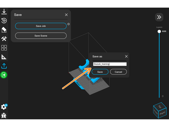
Click the Save tab on the left side of the slicer, and then select "Save Job."
-
Be sure to add the Papercut number to the title of the .NXA file. Save the file locally and upload it to the Papercut order.
-
To print the file, copy the .NXA file onto a USB drive and insert the drive into the printer. Follow this guide for more info.
-


Cancel: I did not complete this guide.
2 other people completed this guide.