-
-
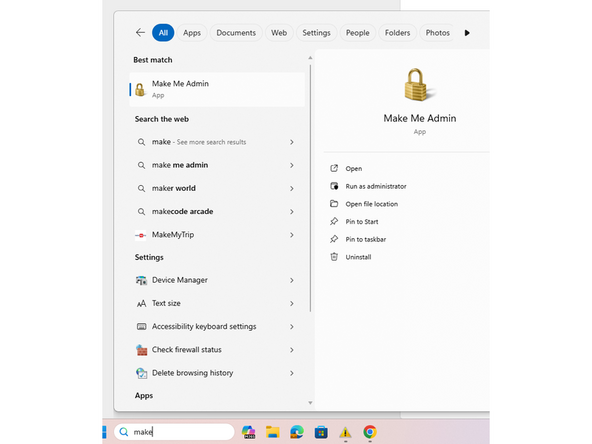
To open the software you must first enable admin permissions for yourself. This is done by launching the 'Make Me Admin' application and clicking the 'grant administrator permissions' button.
-
Next click and run the slicer as with any other program.
-
A popup will appear and ask for an administrator log in. Using your g-suite login (not your ID numbers) you can log in as normal.
-
-
-
The software will then prompt you asking the machine type and material library. For the machine select the ProX200 and for the material select the INC625 database.
-
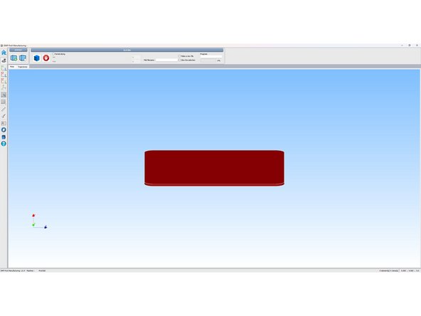
You will then be brought to the home screen of the software.
-
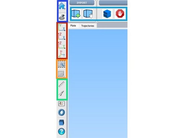
The top button will allow you to open and interact with preexisting files. The lower button hides the plate and object.
-
These buttons from left to right do the following. The left most button allows you to add part files to the plate(stl only?). The next button lets you move the objects around the plate and changes the camera angle to a top down focus. The next button slices the current objects on the plate. The last button stops the slicing progress.
-
These buttons allow you to switch views between different planes and back to the original view of the plate.
-
These buttons control a rectangular zoom and rectangular selection function.
-
These buttons control and angle tool and a measurement tool. They function similarly to the measure command in Solidworks.
-
-
-
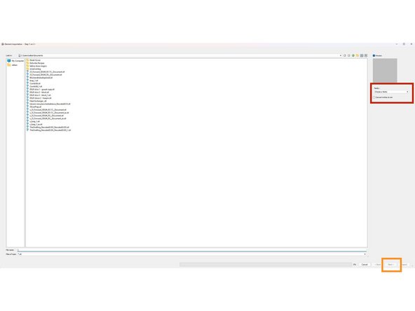
To load a part click the add part button from the earlier image. You will be brought to this screen where you can select the proper directory and part.
-
A preview of the part will be loaded on the right part of the screen. Below the part select the sintering family, For our purposes we will simply select Part Hex sintering. This is the laser family setting and determines the pattern the laser makes when manufacturing the part.
-
Once this is done press the next button at the bottom right of the screen. This will bring you to the orientation screen. WARNING, by pressing import you will skip the support steps and drop the part directly on the plate.
-
As a note for more advanced users if you make custom laser profiles this is where they will be displayed. Additionally the slicer uses different laser settings for different support types. The fine points of this will take a couple of builds to grasp but it is worthwhile to explore.
-
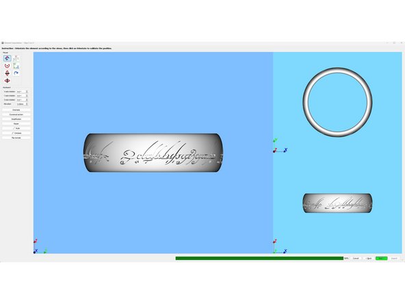
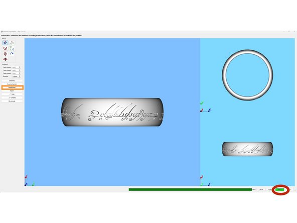
The next screen that you will encounter is the orientation screen. On this screen we will orient that part so that it may be easily removed from the plate in post processing. Additionally you can make changes to the parts orientation in preparation for adding support material to the part.
-
once you press orientate the part is now in that orientation and whatever angles/ height it was at are now considered zero.
-
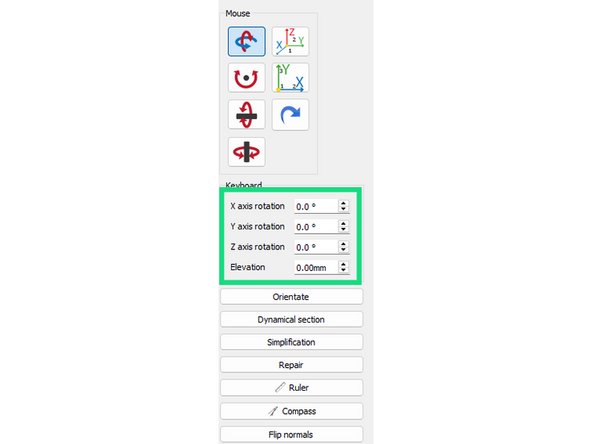
Alter the height of the part to be at minimum 5mm from the base plate by changing elevation to 5mm. Then change the angles to those that best align with DMLS design doctrines. Finally click orientate to lock in the changes.
-
Upon clicking orientate the skin of the part will become colored with green, yellow and red zones. These zones indicate the necessary support level (as determined by the slicer) each polygon needs.
-
-
-
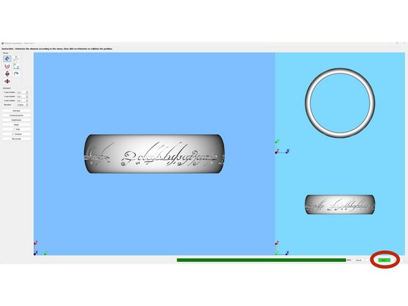
Now that our part is orientated click 'next' at the bottom right of the screen to move to the next step.
-
As a reminder the green sections of the part do not need support. The yellow sections may need support depending on existing geometry in the rest of the part (ask your MS/TC). The red zones require support.
-
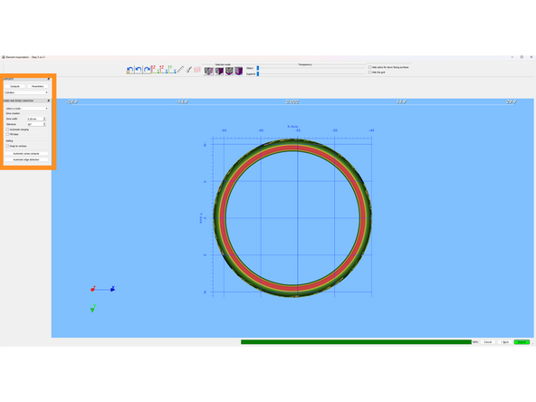
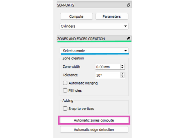
This is the supports menu and is how you modify support structures and support locations on the part.
-
The 'Parameters' button will let you edit each type of support structure individually. You can change things like grid thickness, penetration into the part, and many other aspects.
-
Zones and edges will allow you to control where supports are placed on the part.
-
The select a mode drop down menu will give you 4 options for placing support.
-
The 'Surfaces' option will allow you to select individual triangles or surfaces to place support on. The 'Painting' option will allow you to paint on supports to those specific polygons. By holding control and clicking on more areas you can select multiple surfaces to support.
-
By clicking the automatic zones compute you can select a minimal angle and the program will automatically select those zones for supporting. (Recommended for beginners)
-
-
-
The slicing software is a 32bit program which means that it can run off a max of 4gb of ram.
-
This is obviously bad for for a piece of software meant to handle complex geometries with lots of data. As such sometimes when slicing a part the software will crash and you will have to start over.
-
Brute forcing the part through is unlikely to work so we can use the mesh simplification tool inbuilt to the slicer. This will lower the part quality by combining some of the triangles already on the part but you will be able to slice the part.
-
The simplification tool is here.
-
-
-
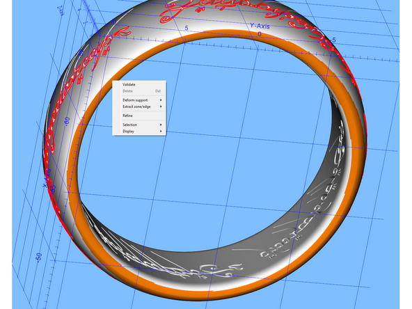
Once you have all the zones highlighted that you want to support you must validate the support. This is done by right clicking the orange highlighted zone and clicking validate.
-
The highlighted zone will now turn blue indicating that it can be supported. Clicking the blue zone will turn it purple indicating that the zone is selected for support.
-
Select the desired support type from the support menu and then click compute. This may take some time depending on the part but support geometry will be generated.
-
In order to properly print some pieces it may be necessary to have multiple supporting geometries for different sections of a part. Knowing what support to use where will take some time and experience that you can only build by making mistakes.
-
You can also deform support and move the angle at which it rests by right clicking the support then hovering over support deformation and clicking free deformation.
-
This will allow you to move the angle of the support relative to the part. by default you make a sort of scaffolding
-
Once the desired support configuration has been achieved press next to move to the next step.
-
-
-
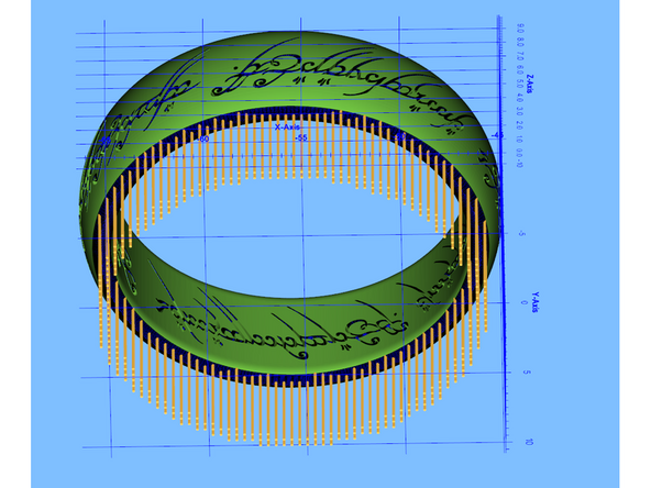
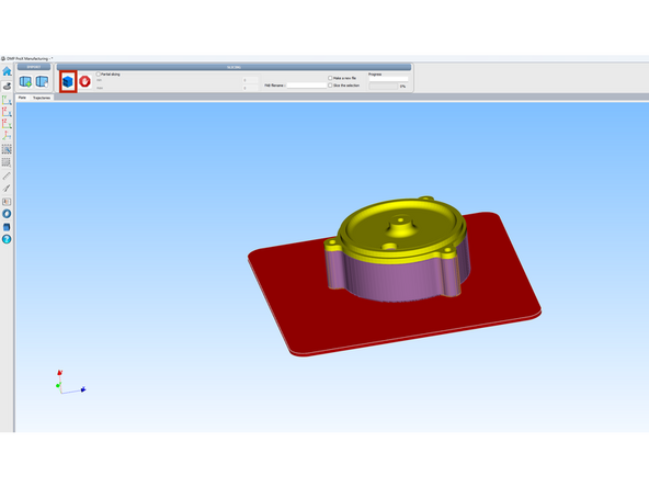
This is what the part looks like when it is supported and ready to be sliced for printing.
-
In the top left corner of the screen you can press the slicing button to begin the slicing process.
-
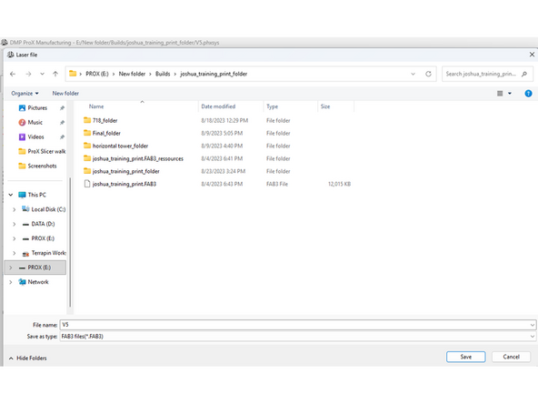
Press ctrl + s to save the part as a phxsys file.
-
This will save the part as it is and the slicer will be able to open to this exact point where you can make changes as you need to.
-
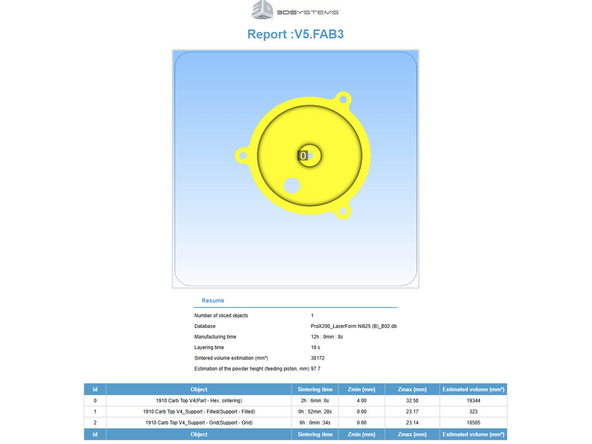
Save the file as a fab3 file which is what the ProX reads. This will begin the slicing process. After a report is generated in HTML the physical requirements of the part will be shown which you can use for pricing.
-