-
-
In FDM, when plastic is extruded from the nozzle it's cross section is circular with a diameter the same as the nozzle's. {Picture 1}
-
A circular cross section has very little contact with the surface, and a small contact area means poor bed adhesion.
-
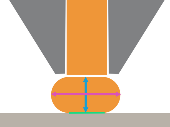
To resolve this issue, the nozzle is lowered so that the height is less than the nozzle diameter. This causes the extrusion to squeeze outwards into an oblong cross section, providing significantly more contact area. {Picture 2}
-
The "goldilocks" zone for layer height is between 25% and 75% of nozzle diameter. Going below 25% can potentially clog the nozzle because there is not enough room for the extrusion to leave the nozzle.
-
The squeezed extrusion is described by its cross sectional dimensions.
-
Layer Height
-
Extrusion Width
-
-
-
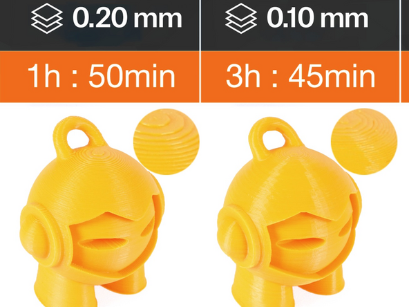
Layer height majorly impacts Print time, but has an inverse effect on Vertical Resolution.
-
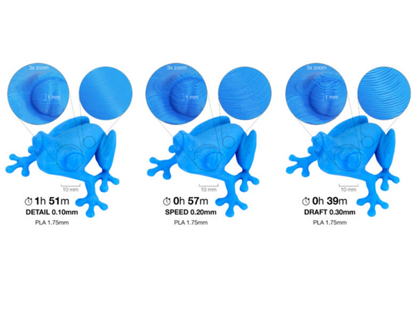
Tall layer heights significantly shorten print times but are more visible. Inversely, small layer heights are less noticeable at the cost of longer print times.
-
Tall layer heights are most noticeable on surfaces that are sloped or curved vertically, where you will see noticeable steps. Reorienting is often a useful tool to counteract this behaviour.
-
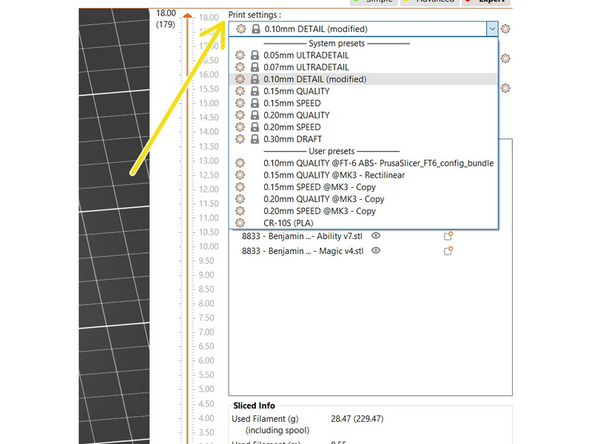
The layer height is at the start of every profile's name, followed by a descriptor of the quality that profile has been optimized for. Profile selection is the primary way to select layer height in a slicer.
-
0.10mm is the minimum layer height used in the FabFarm unless approved by a manager. The improvement from 0.10mm to 0.07mm or 0.05mm layers is minor with significantly longer print times.
-
-
-
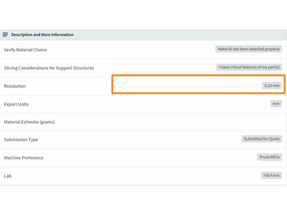
Customers can specify a layer height for their order. This is called 'Resolution' in Papercut.
-
It is vital to follow customer specifications. If a customer does not select a resolution, it is up to us to select an option that will balances quality and efficiency.
-
This is especially important in the The Fabrication Farm which regularly deals with high demand.
-
-
-
A slicer creates the same general structure on every layer: several loops around the exterior of the object, and then a repeating pattern to "fill in" the interior.
-
The exterior loop(s) are called perimeters, and
-
the interior pattern is called infill.
-
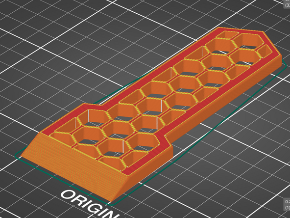
We will be using the scraper model seen in the Picture 2 as an example in this guide. Optionally, you can download the model here and follow along with the guide.
-
-
-
Perimeters print first each layer, starting with the exterior perimeters and moving inwards.
-
Picture 1 show the perimeters of the first layer of the scraper. The infill is hidden.
-
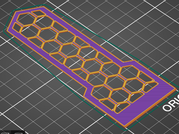
Exterior perimeters are highlighted orange in Prusa Slicer sliced view.
-
All other perimeters are highlighted yellow in Prusa Slicer sliced view.
-
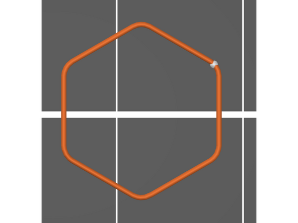
Exterior perimeters will always print in a complete loop, ending at the same place it started. This point is called the seam and is often visible on the surface of the printed part.
-
There are 31 exterior perimeter loops for the scraper. Each will have their own seam. Picture 2 shows just the first loop printed. The white dot is the seam.
-
By default, each loop's seam will start at the same location on every layer. This behaviour can be modified to randomize the seam's location on each layer. This is solely an aesthetic decision.
-
If following along in Prusa Slicer, see if you can replicate the images in this guide using the sliced view legend, layer slider, and print move slider. These tools are helpful for understanding what the printer is going to do before sending a print.
-
-
-
Unlike perimeters, infill will change significantly across the print.
-
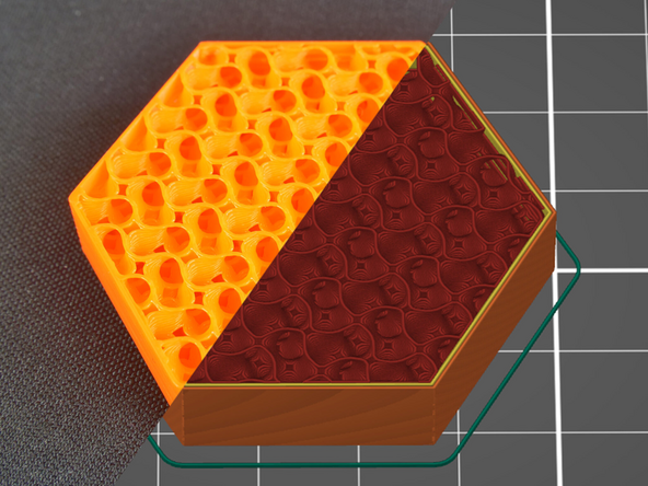
For the first several layers, infill regions will print with Solid Infill, colored purple in Prusa Slicer. {Picture 1}
-
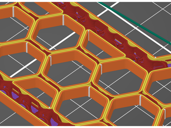
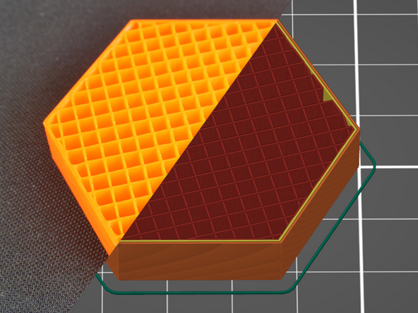
After solid infill, the infill regions will print with Internal Infill, colored dark red in Prusa Slicer. {Picture 2} Instead of printing solid, internal infill typically has voids. This conserves material and print time.
-
Internal infill is often just called "infill", which can cause some confusion.
-
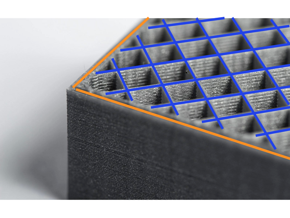
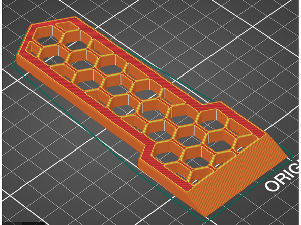
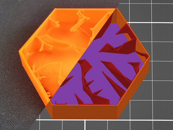
After internal infill there is one layer of Bridge Infill, several more layers of solid infill, and then a final layer called Top Solid Infill, colored bright red in Prusa Slicer. {Picture 3}
-
Bridge infill orients the moves to shorten the paths across voids, bridging the gaps more easily. It is also used on external surfaces when crossing bridges as discussed in the Support Generation guide.
-
Top Solid infill typically prints more slowly than solid infill to create a higher quality surface.
-
The scraper model only has one infill type per layer. In more complex models like these animal busts, there may be multiple types of infill in each layer.
-
-
-
The internal infill of a 3D print is primarily described by the infill density and the infill pattern.
-
The density is displayed as a percentage, corresponding to the ratio of material to void. A print with 100% infill density would be solid, a print with 0% infill density would be hollow.
-
Printing completely solid can be difficult for 3D printers to complete successfully due to a build up of heat. Conversely, hollow 3D print may be unable to support top solid layers.
-
15% infill density is standard on most profiles, as it provides sufficient support while saving on material and time.
-
Prusa Slicer offers a variety of infill patterns for both internal infill, and for the top and bottom infill. Internal infill pattern has an effect on print time, filament usage, and part durability, while top and bottom infill are aesthetic choices.
-
Infill patterns can be selected under Print Settings / Infill.
-
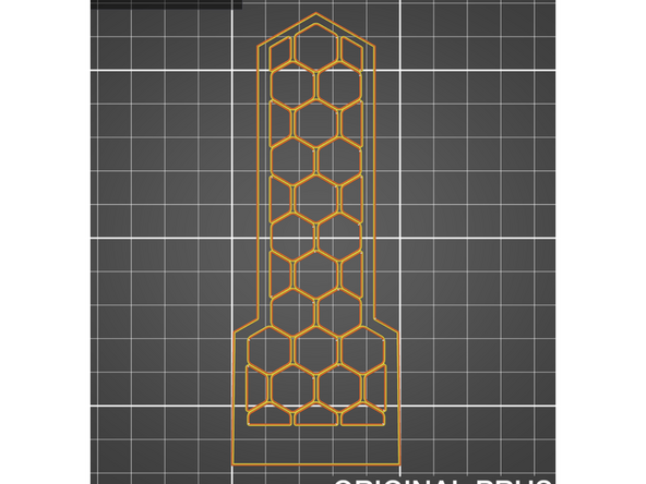
Read the introduction of this article and the sections on Gyroid {Picture 1}, Rectilinear {Picture 2}, and Lightning {Picture 3} to see common options.
-
-
-
Perimeters and infill are commonly used to adjust the durability of a part.
-
Internal infill is often mistakenly thought of as having a larger effect.
-
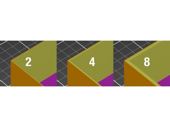
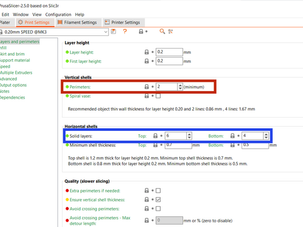
Increasing the number of perimeters and the number of top and bottom solid layers, collectively called the Shells, is a more efficient and effective option to consider when looking to increase a parts durability.
-
The number of perimeters (vertical shells) and top and bottom solid layers (horizontal shells) can be modified under Print Settings / Layers and Perimeters.
-
-
-
Unlike resolution, there is no specified area in Papercut where the customer can select perimeters or infill settings.
-
If customers have requirements on either, they will add those in the "Additional Instructions" or comments at the bottom of the ticket
-
-
-
Download each of the models from this folder. Write down an answer to each models question. Your mentor will review your answers once complete.
-
Low Poly Bunny - What are the print times for this model using the following layer height profiles? This model does not need supports. .30mm DRAFT, .20mm SPEED, .20mm QUALITY, .10mm DETAIL
-
The ‘.20mm S’ profile primarily decreases print time by doubling the speed of internal infill printing compared to the other profiles. When swapping profiles from ‘.20mm Q’, what has a greater effect: Doubling the speed of infill printing as in ‘.20mm S’, or Increasing the layer height as in ‘.30mm D’? Is the difference in effect significant?
-
Half Cylinder - There is one distinct orientation that is superior for printing. What is it and why?
-
Swap to the 0.30mm layer height to spot the issue with the incorrect orientations more easily.
-
Flexi-Rex - The links of this “flexible” model are the most likely failure point. What number of perimeters will maximize link strength? Why would increasing it further have a minimal effect?
-
Use the sliced view layer slider to look at the interior of the links.
-


Once completed this guide, please make sure you notify a TS so they can check you off
Once completed this guide, please make sure you notify a TS so they can check you off
Cancel: I did not complete this guide.
5 other people completed this guide.
