-
-
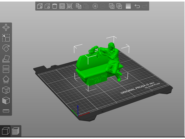
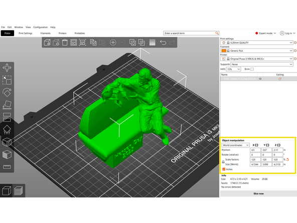
A slicing software provides a virtual build plate to arrange orient models for printing.
-
-
-
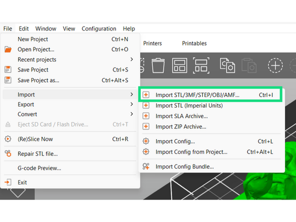
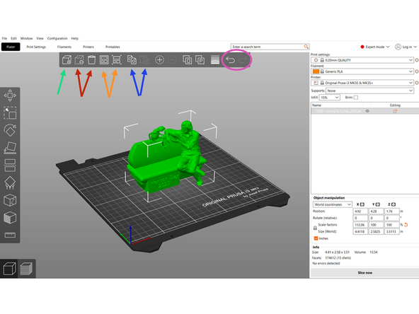
This icon is used to add in STLs to the virtual build plate.
-
The first of these icons is used to remove a selected model from the build plate.
-
The trash can icon will clear the entire buildplate
-
The fourth icon will arrange all the objects in the file, creating multiple build plates if necessary
-
We often use the terms build plates and beds interchangeably. Both refer to the surface the printer prints on. Multiple build plates will therefore entail multiple prints.
-
The fifth icon will arrange all of the objects on one build plate, deleting any objects that don't fit
-
These two icons copy and paste objects. You can also use CTRL+C and CTRL+V.
-
The last two icons allow you to undo and redo
-
-
-
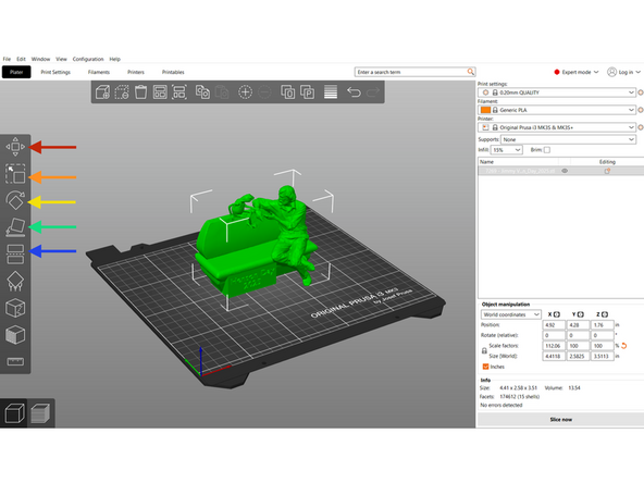
The left toolbar allows you to manipulate object(s) on the virtual build plate. These tools are only available after an object has been selected.
-
From the top down:
-
Moving
-
Scaling
-
Rotating
-
Placing on face: Select a face to place on the virtual build plate
-
Cutting
-
The bottom icons are used for paint-on supports, seam painting, paint on texture, and measuring. The first two of these will come later in training, the others are rarely used but feel free to mess around with them or ask a TS
-
-
-
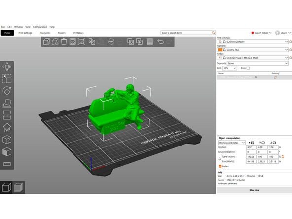
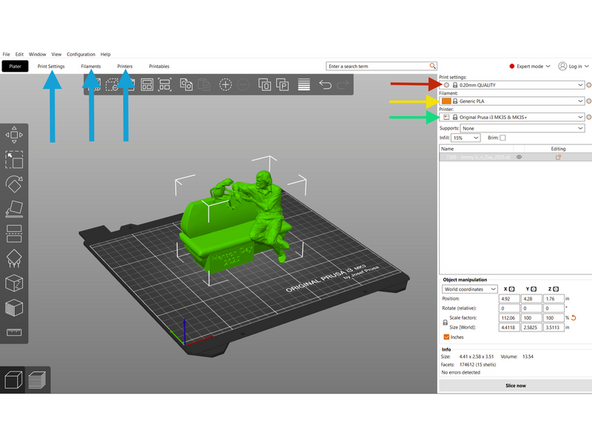
Profiles are preset settings packages. We typically use the default profiles provided by the slicer, but custom profiles can also be created. For each print we will need to select a Print Profile, a Filament Profile, and a Printer Profile.
-
This dropdown lets you choose a Print Profile. The print profile determines most of the settings.
-
Our default profile is "0.20mm QUALITY".
-
We often change print profile based on customer needs.
-
This dropdown lets you select a Filament Profile. The filament profile tells the slicer what type and brand of filament we are using, and determines filament specific settings like print temperature. We typically use the "Generic" brand filament profiles.
-
This dropdown lets you choose a Printer Profile. The printer profile tells the slicer what model of machine we are using. Only options selected in the configuration wizard will appear.
-
The printer profile will often include the size of the nozzle loaded on the printer in the title. Most of our printers are loaded with a 0.4mm nozzle.
-
All profiles can be edited from the top toolbar. There are many settings that can be edited.
-
-
-
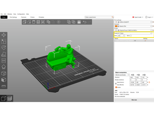
The section below profile selection has tools to add/edit supports, infill percentage, and brims.
-
Supports and infill are a fundamental part of the 3D printing process. Both are covered in detail in future Dozukis.
-
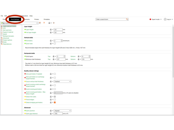
Under the print settings tab, every aspect of the slicing process can be modified. The most common advanced settings include:
-
Number of shells/perimeters
-
Infill pattern
-
Support type
-
Print speed
-
-
-
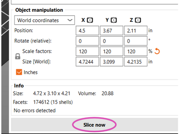
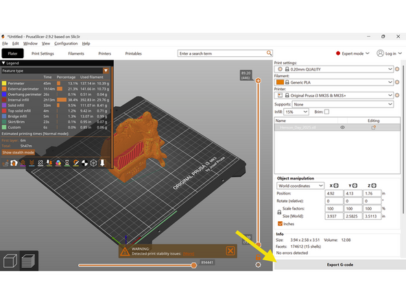
When an object is selected, the Object Manipulation Panel will appear. It provides several input fields for accurate control.
-
Position
-
Rotation
-
Scale - Apply a size multiplier expressed as a percentage, uniformly or to individual directions.
-
Size - Set exact dimensions in either inches or mm.
-
-
-
Once the object(s) are prepared with proper settings, you can select Slice now. The software will take our inputs and generate instructions for the machine.
-
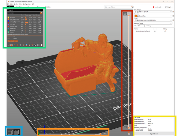
Once a part has been sliced, you can select sliced or unsliced view at the bottom left.
-
In sliced view, you can see a preview of the instructions the software has generated. The model will now be "sliced" into layers.
-
You can preview the different layers with the vertical slider on the right
-
You can preview each move the nozzle with make with the horizontal slider on the bottom. As you look through each move, you will also see the corresponding gcode command in the bottom left.
-
The model will be color coded following the key in the top left.
-
At the bottom right there is a section titled "Sliced Info". The two most important pieces of information in this section are "Used Filament (g)" and "Estimated Printing Time."
-
-
-
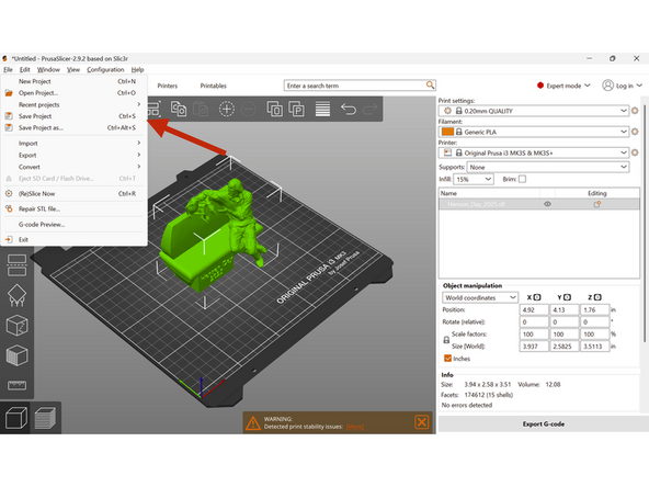
It is important to save progress so that we can return later and continue work or edit what has already been done. GCode files are not easily editable, so we must save the project as a 3MF file if we wish to return to it in the future.
-
To save, click File and then Save Project or Save Project As, or by hitting CTRL+S.
-
This will save everything to a .3mf file.
-
After slicing, export by clicking Export G-Code.
-
Both 3MF and GCode should be uploaded to the PaperCut Order after slicing
-
When finished walking through the User Interface Guide, have a TS check you off. They will then give you an .STL to upload. Play around with the settings until you feel comfortable with the covered concepts in PrusaSlicer.
When finished walking through the User Interface Guide, have a TS check you off. They will then give you an .STL to upload. Play around with the settings until you feel comfortable with the covered concepts in PrusaSlicer.
Cancel: I did not complete this guide.
2 other people completed this guide.
