Tools
Parts
No parts specified.
-
-
There must be at least one other person in the IFL with you when use the surface grinder.
-
Be sure to get protective eyewear when you walk in the door.
-
Alert the staff you're going to use the Trak DMP RX2 for the ProX plate.
-
-
-
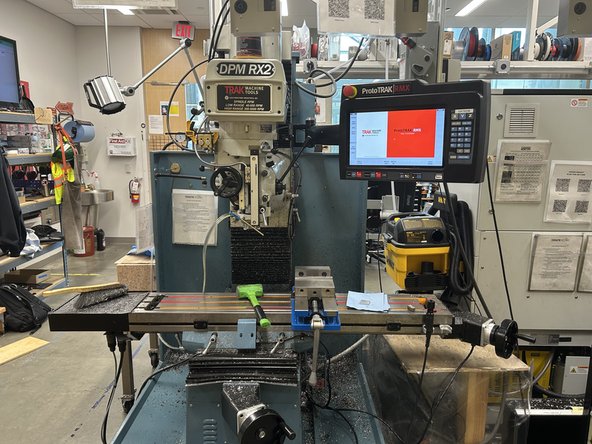
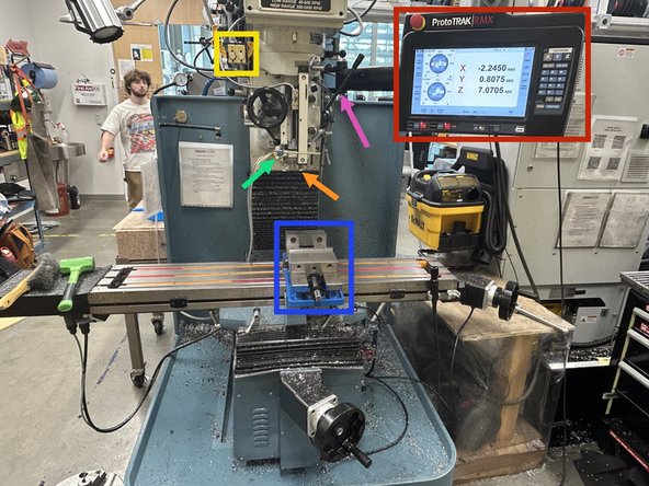
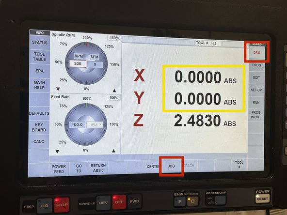
At the top right is the touch screen interface where you will be interacting with the resurfacing program and setting your zeros.
-
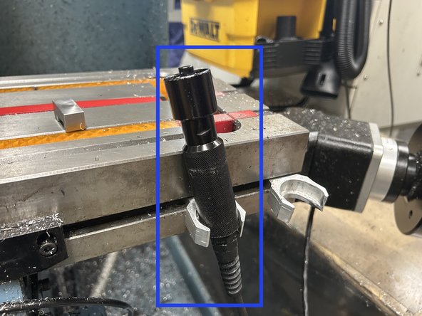
Front and center is the tool slot where your face mill bit and zeroing spindle will attach to.
-
In the top left is the pneumatic tool clamp. Pressing "in" will cause a tool placed in the tool slot will cause it to be secured in place, "out" will cause it to be released. This may be loud.
-
Next to the tool slot is the accessory blower. This can be configured to dispense air or cutting oil, for the purposes of resurfacing plates only air should suffice.
-
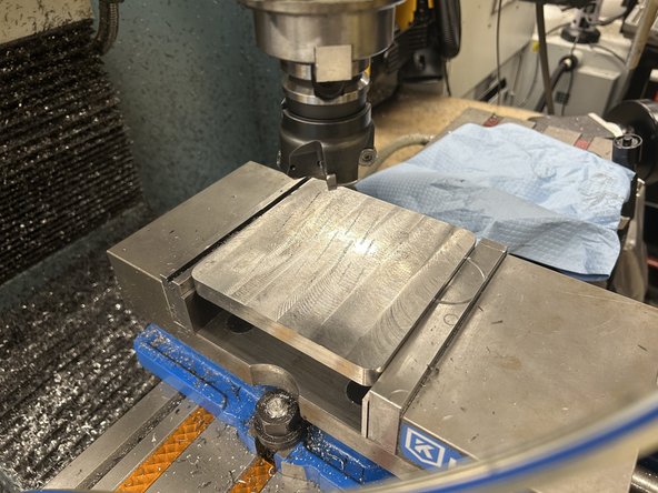
Below the tool slot is the part vice clamp which holds the build plate in place. Note that the build plate must be sat upon two spacers which hold it high enough to clear the edge of the clamp jaws.
-
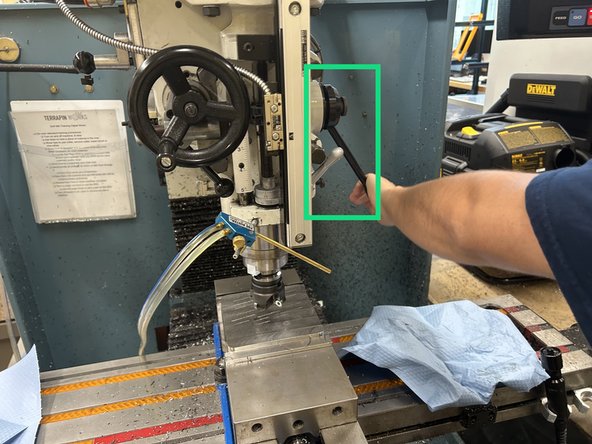
On the tool column is the height adjustment lever which allows the tool to be moved downwards by a certain amount for zeroing purposes. This must be set in the up position whenever not in use.
-
-
-
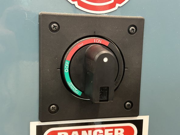
If the Trak is not already turned on, go to the back of the machine and turn the switch to the "on" position.
-
-
-
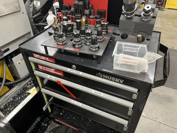
From the parallels drawer to the right of the Trak, select a pair of parallels which will hold the build plate up so that the top of the build plate clears the edges of the clamp jaws. (the 1 3/8" offsets are typically preferable here) The goal is to elevate the surface for the plate to be ~1/8in above the jaws.
-
Using the detachable metal vice handle, open the vice clamp until the build plate just fits.
-
Now place the build plate within the jaws on top of the parallels you select and clamp it in place using the detachable handle. Hammer the corners of the build plate flat onto the parallels with the green mallet to ensure the the build plate is level and firmly set in the jaws of the clamp.
-
Put the handle back in its holder when you are finished with it.
-
-
-
Our program is loaded onto the black flash drive E which should already be inserted into the machine. If not, it can usually be found next to the computers. Otherwise ask an IFL staff member for assistance locating it.
-
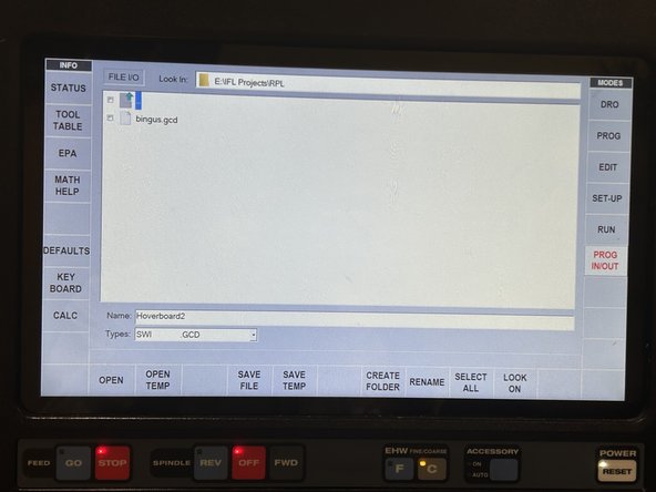
Press the PROG IN/OUT button on the right side of the screen and navigate to the RPL folder inside the IFL Projects folder.
-
Press on and open the file titled "bingus.gcd" (yes really).
-
-
-
Now replace the tool head with the 4-flute face mill from the tool head tray using the pneumatic tool chuck.
-
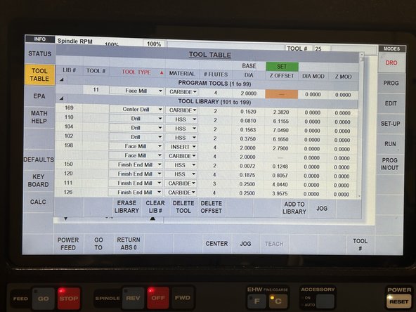
Press on the tool table tab on the left side of the interface screen.
-
Select "face mill", "4 flutes", "2 inch diameter", and set the z-offset to 0.000.
-
-
-
Next we need to set the zeros for the tool head and vice clamp for the program to reference while running. Press DRO and then JOG on the touch screen.
-
Using the wheel on the right to adjust the side-to-side position of the plate and the front wheel to adjust the forward-to-back position of the plate, position the plate directly under the face mill so that the center of the face mill is directly above the center of the build plate.
-
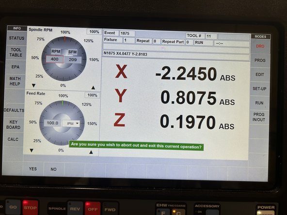
Now press the X button to the right of the touch screen, and then ABS SET. Then press the Y button, and then ABS SET again. This will set the X & Y axis zero for the mill.
-
With the tool head centered above the build plate, use the height adjustment lever to gently lower the tool head onto the surface of the build plate. Use the small silver lever beside the height adjustment lever to lock it in place temporarily.
-
The height adjustment lever may fling upwards unexpectedly when unlocked, keep a hand on it and guide it upwards gently.
-
Now press the Z button to the right of the touch screen, and then ABS SET. Then release the silver lever and push the height adjustment lever all the way in the upward position.
-
-
-
Now that everything is set up, we can begin the resurfacing by first pressing the Accessory On/Off button underneath the screen to turn on the blower. Point the blower towards the leading edge of the face mill.
-
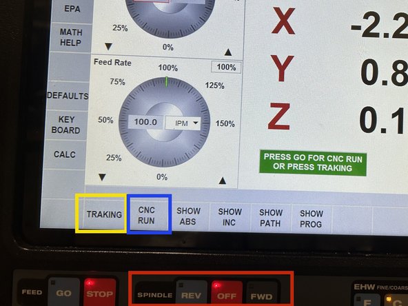
FWD button below the screen to begin spinning the tool head. (keep in mind that long sleeves and hair must be kept a long distance away from fast spinning objects like this)
-
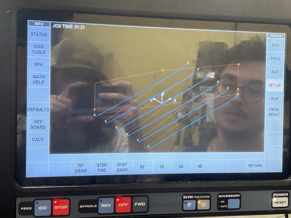
Press TRAKING to begin moving the tool head to the start position and along the projected tool path by turning the wheel at the front of the machine. This mode gives operators manual control over the speed that the tool head has while executing its programmed path.
-
Make sure the feed rate button below the screen is set to Fine as the goal is to move the tool head at about 4" per minute. Check that the tool head isn't too far up or down, and the plate is level.
-
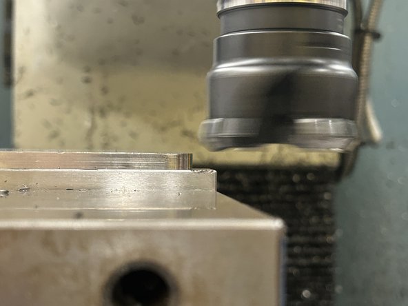
After the tool head has made one full pass over the build plate, and the cut looks level and clean, press CNC RUN to allow the program to run automatically. Hold the Stop/Start wand and keep a close eye on the machine until the CNC run is complete. Press the button when you want to stop or resume the program.
-
-
-
The program is set to lower the height of the build plate 4 times to guarantee that all support material is totally removed from the surface, and only smooth steel is exposed. It may not be necessary to wait through all 4 resurfacings, but you must allow it to run at least twice to produce a smooth surface without burred edges.
-
Do not attempt to stop the resurfacing mid-cut unless an there is an emergency.
-
When you are ready to end the program, press the Stop/Start button on the wand to halt the movement of the build plate and tool head. Now press the OFF button under the touchscreen to stop the tool head from spinning, and toggle off the accessory to stop the compressed air.
-
Press DRO on the interface touchscreen; this will cause a prompt asking if you want to abort and exit the program. Press YES.
-
Now press JOG and use the X, Y, and Z controls to move the tool head above the build plate and safely out of the way.
-
-
-
Use the pneumatic tool clamp to release the face mill bit and return it to its proper slot on the cart.
-
Use the removable vice handle to remove the build plate and parallels, placing the parallels back in the container you found them in, and put the container back in the parallels drawer.
-
When handling the build plate, be careful not accidentally put greasy fingerprints on the build plate surface. Wrap it up in a paper towel to protect it and any surface you place it on from getting knicked or chipped.
-
CLEAN UP THE WORKSPACE! As guests in the IFL, it is our responsibility to leave the space as clean (preferably cleaner) than it was when you got there. Use the brush and paper towels to wipe away chips and dust that may have accumulated on and around the machine.
-


Cancel: I did not complete this guide.
2 other people completed this guide.