
-
-
Connect to RPL Wi-Fi
-
Open PreForm.
-
Under Printer, select VernerableYak
-
Select apply
-
-
-
If you cannot find the printer using the RPL Wi-Fi, you can connect to the printer directly via its IP address.
-
Under "Job Setup" select the drop-down arrow.
-
Select "Add"
-
Enter printer IP Address
-
Reference "Formlabs Fuse 1 Menus" step 5.
-
Select "Connect". Select "OK"
-
Select "Apply"
-
-
-
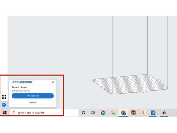
Make sure you are signed into your FormLabs account in the bottom left.
-
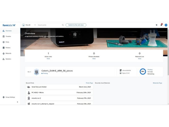
Clicking my account will bring you to the Formlabs Dashboard.
-
The Dashboard allows you to track print progress and receive notifications from the printer.
-
-
-
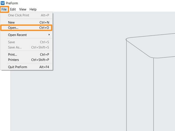
Go to File (top left)
-
Go to Open
-
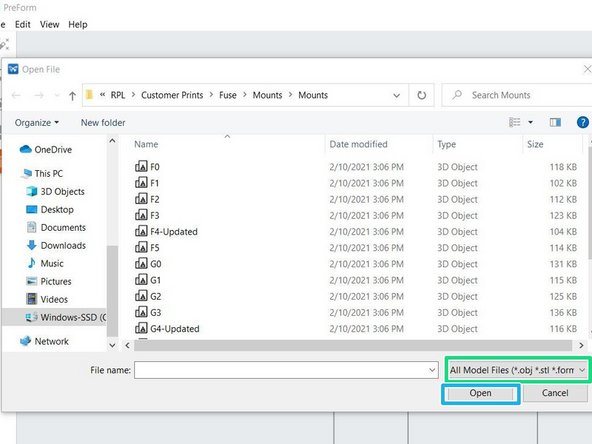
PreForm accepts three files types: .obj, .stl, .form
-
Select all files and select Open
-
-
-
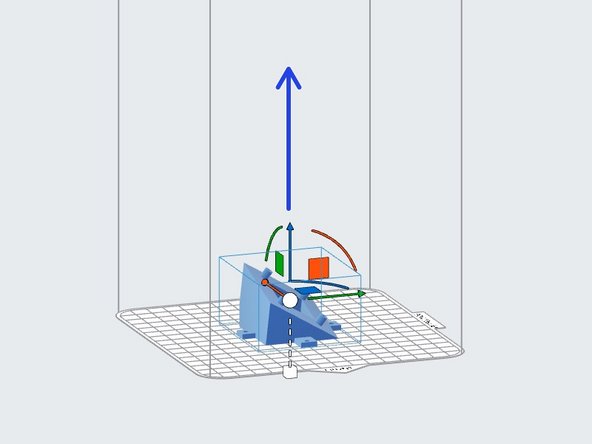
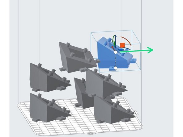
To change the location of a part, it must be selected first. Once selected, it will be highlighted blue.
-
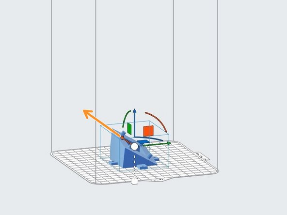
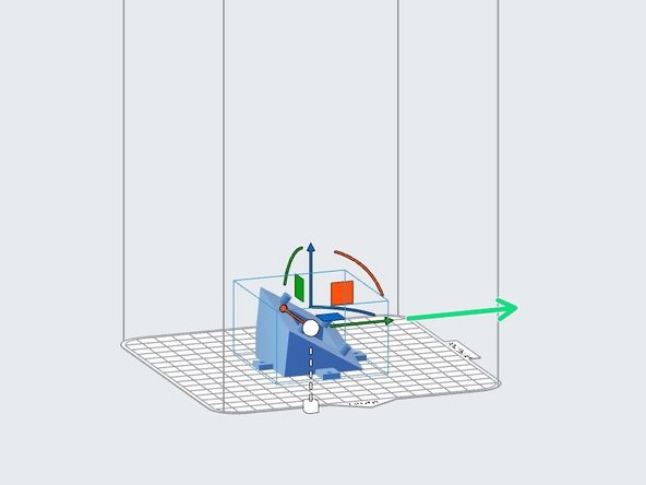
Parts can be translated in 3 dimensions.
-
Blue arrow for Z direction
-
Orange arrow for Y direction
-
Green arrow for X direction
-
-
-
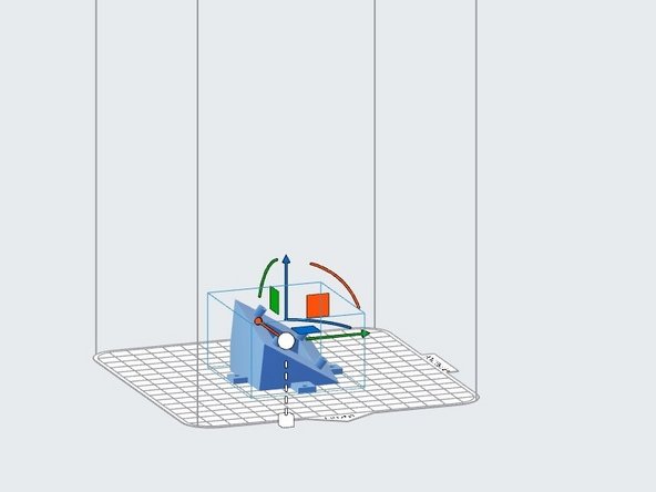
Parts can also be rotated in 3 dimensions
-
Blue arc rotates about Z axis
-
Orange arc rotates about Y axis
-
Green arc rotates about X axis
-
-
-
On the left side of the screen you will find 5 options.
-
1 click print
-
1 Click Print is not utilized.
-
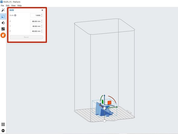
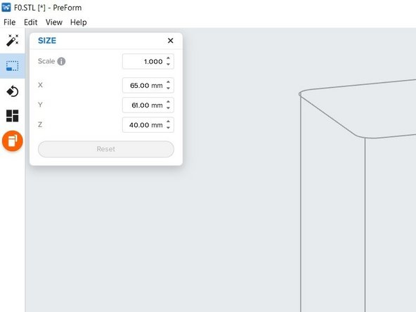
Size
-
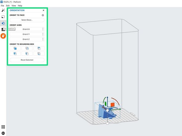
Orientation
-
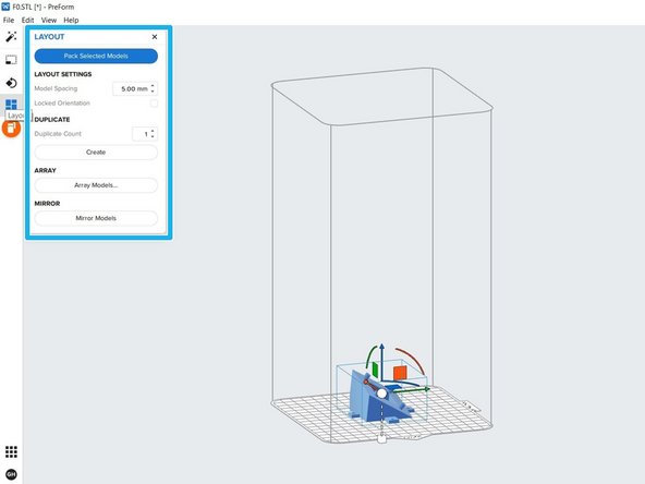
Layout
-
Start a print
-
-
-
Can be used to scale a part absolutely or relative to X, Y, or Z direction
-
-
-
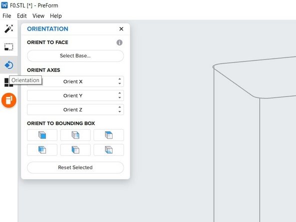
Allows you to select how the part will be oriented
-
You can select a face of the part to snap downwards
-
Top face selected
-
Selected face now snapped downward
-
You can change the orientation of each of the coordinate axes
-
TIP: Orient parts so that finer details lay in the XY direction. The laser is more accurate than layer height.
-
-
-
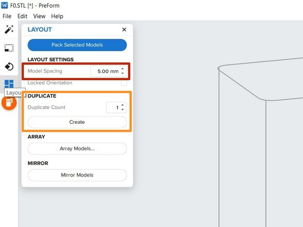
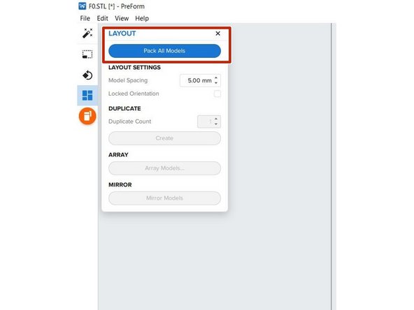
Allows you to change model spacing
-
This is the amount of space between parts in the build chamber.
-
5 mm is good, but should not drop below 3 mm.
-
Duplicate
-
Will make a duplicate (copy) of a selected part for a selected quantity.
-
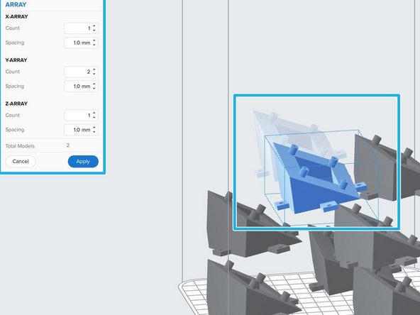
Array/mirror models
-
Array models will create a linear arrary for a selected part
-
Mirror models will mirror a part across the x-axis
-
-
-
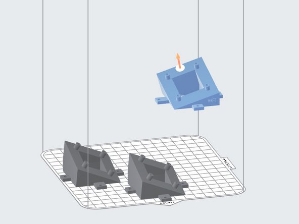
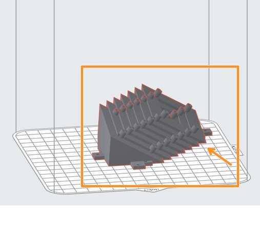
Parts should be packed as low as possible.
-
Bad packing.
-
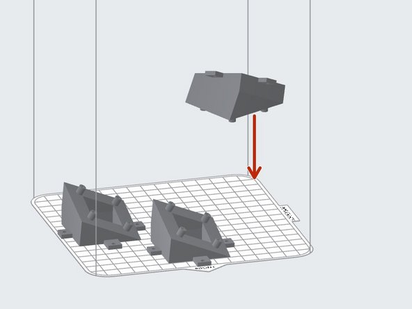
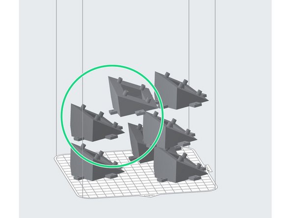
Good packing. (After using packing feature)
-
The higher your parts are in the build chamber, the longer your print will take.
-
Packing feature.
-
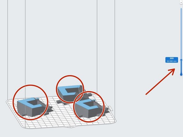
When parts become highlighted in red, this means that they are touching and overlapping.
-
The “Pack Selected Models” button will automatically pack all models in a way that is acceptable. However, this may require slightly more manipulation as it may not be the most efficient way to print. (The lower your parts, the better).
-
-
-
Cross Sections
-
The slider on the right side of the screen allows you to see the individal layers. It displays layer number and current height in mm.
-
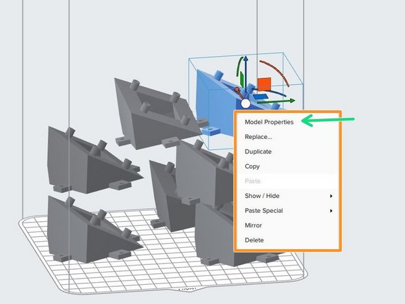
Right-Clicking a part
-
Allows quick part manipulation such as replace, duplicate, and copy.
-
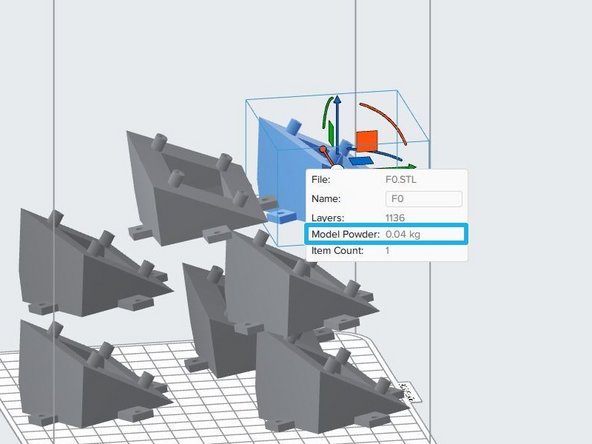
The "Model Properties" option can be used for quoting customers.
-
It will display the amount of powder that will be used for that particular part.
-
-
-
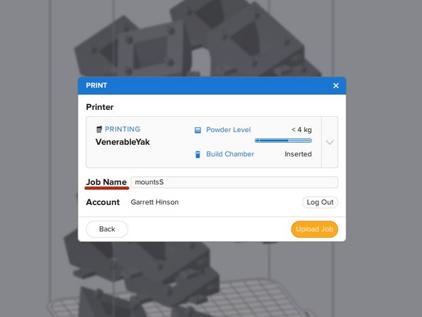
Allows you to upload the current job to the printer.
-
Make sure to change the Job Name to PC#XXXX CUSTOMER_NAME.
-
Select Upload Job.
-
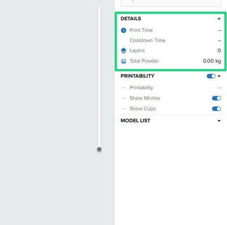
Select Upload Job. Take note of "Total Powder, Print Time, and Cooldown Time" on right side of screen.
-
In order to calculate the print time, you must click on it.
-
If the "Total Powder" exceeds the current amount of powder in the Fuse, add more. *refer to Preparing the Fuse to Print Dozuki.
-


Cancel: I did not complete this guide.
4 other people completed this guide.