Introduction
This training guide will take you through each CAM step in Fusion 360 for machining the UMD-M training part.
-
-
Open fusion and switch to the IFL team.
-
Select Router project in the left side panel. In the training folder select UMD-M to open the CAD file.
-
-
-
Open drop down menu and select Manufacture.
-
Select setup button to create a new setup. (Only one setup will be used for this part.)
-
In the setup editor to the left, we will create the stock for this part as well as select our origin. This origin is where our three zeros will be located.
-
In setup tab, make sure that the origin is located at the top-middle of the stock. If not already selected, click on the stock point to make the origin.
-
In stock tab, select fixed sized box. It should do it for you, but make sure the model fits inside the stock and that the stock is .75" tall. (This is the size of the material available). In model position drop down select offset from bottom and set offset to zero.
-
In post-process tab, create a program name and comment so you can find it later.
-
STOCK = .75"
-
-
-
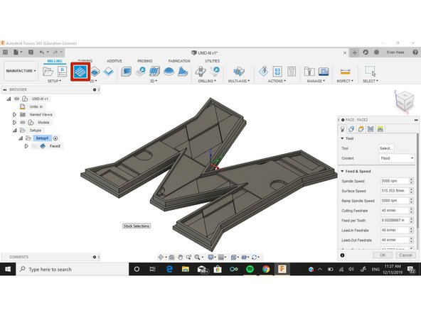
For the first operation, we want to use the face tool to face off the extra stock above the part. Select "Face" in the 2D section above. This will open the facing menu to the left.
-
This menu has the settings that will control the facing operation. We will not need to change the Geometry, Heights, or Linking settings for facing.
-
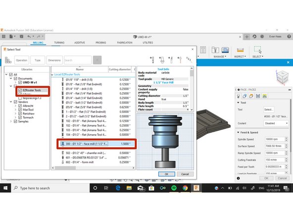
In the tool tab click select tool to open the EZRouter tool library. Inside the tool library select the face mill. When tools are imported, they will change the feeds and speeds in the tool tab depending on what tool it is. Each router tool is already set to cut MDF so the feeds and speeds do not need to be changed.
-
In the passes tab, we only need to change the stepover and stepdown for the face mill. The stepover should be set to 1.25 and stepdown is 1/8". These may be changed in the future.
-
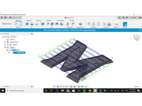
Once settings window is closed Fusion will show the tool path of the face mill over the part. During the camming process if you ever want to check your work, right click on your setup and select simulate to view the progress of the part.
-
-
-
Next operation is an adaptive clearing. We want to remove as much material as quickly as possible while leaving a small amount for the finishing operations.
-
Start an adaptive clearing and select the 1/2" Anama end mill (our largest end mill). Once again, feeds and speeds are already set for the tool.
-
Geometries tab settings are already set.
-
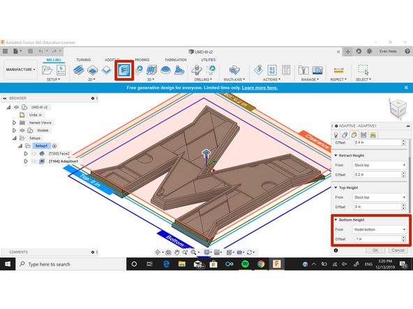
In the heights tab, we only need to change the bottom height so that there is material left. There needs to be extra material on the bottom so that the part does not move during the other operations.
-
Set bottom height as .1" offset from bottom of the stock. This should be enough to keep the part secure. This value will be used for all outside machine operations.
-
In the passes tab, some values we need to change for an adaptive cut are optimal load and max roughing stepdown.
-
Set optimal load as .25" (1/2 the tool diameter is usually what we like to use). Set stepdown as 1/8". Depending on what kind of finish you want for your part, these values can be changed.
-
-
-
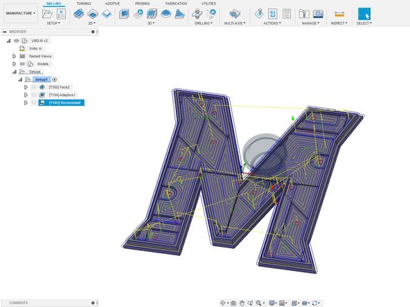
The horizontal operation will cut all flat surfaces of the part.
-
Select horizontal from 3D operations and choice the 1/8" bit from the EzRouter tool library.
-
Turn smoothing on in the passes tab and hit OK. It will automatically create a tool path for all surfaces for you.
-
-
-
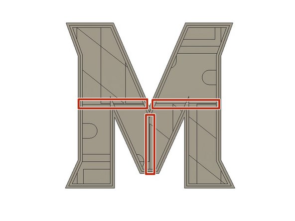
For the 2D contours, we will finish any edges we missed and cut away the remaining part lines.
-
The 3 lines cutting the M in half shown in the picture were too small for Fusion to cut because they are smaller than the 1/8" bit. We will have to manually select this lines and use 2D contours.
-
There are a few ways of doing this but one way is drawing addition lines in the design.
-
Go to the design tab and draw 3 lines as seen in the picture.
-
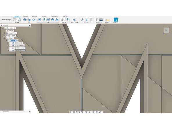
Go back to manufacture and select these lines as the 2D contour lines.
-
If in the simulation it cuts too much off, try changing the tangential extension in the geometry tab.
-
Another option is to select the bottom edge of the each of the three cuts. Make sure the horizontal ones are coincident.
-
-
-
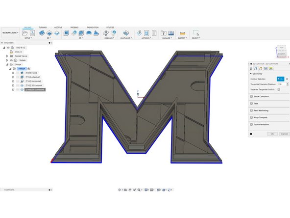
For the final operation we will be using a 2D contour to remove the part from the stock.
-
Select 2D contour and pick the bottom edge of the part shown in the picture.
-
In the heights tab, change the bottom height to -.01 inches from the stock bottom. This will ensure that the part is fully removed from the stock.
-
Upload a final picture of your cutout "M"
-