Tools
Parts
No parts specified.
Featured Document
-
-
Here is a link to download the PDF drawing
-
-
NOTE* THIS DOZUKI CAN BE COMPLETED MANY WAYS
-
1) If you are already familiar with Fusion 360, then use the drawing to complete the part
-
2) If you are competent, but still not sure about some feature, just skip to the Step with the feature you need help understanding
-
3) If you are not sure about how to start, follow this dozuki through its entirety, and it will walk you through start to finish
-
-
-
This step is not necessary and can be skipped
-
When we begin drawing a CAD file, it is a good practice to observe the part
-
From here we began by creating 2D shapes.
-
We then use these 2D shapes to create 3D objects in space.
-
The picture is a highly detailed flow chart of the engineering design process.
-
-
-
Start the program Fusion 360
-
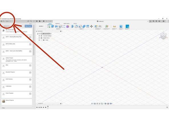
Select your name on the top right of the screen
-
Make sure the "IFL - Team" is selected
-
Select "IFL - Team"
-
If "IFL - Team" is not available, contact either David Kriesberg or Kenny Davis Jr to be added
-
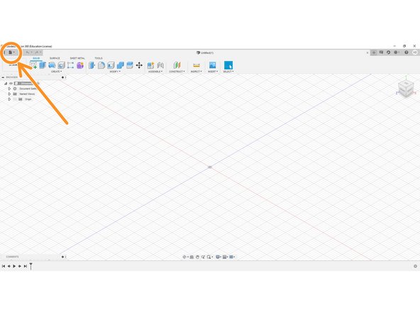
Began by clicking the file button (circled in orange), and select "New Design"
-
This can also be accomplished with Cntl+N
-
-
-
As with every CAD file, we will begin by creating the most basic shape
-
Looking at the CAD drawing, we see that a RECTANGLE is the most basic shape, so keeping that in mind, we will start a new sketch
-
Remember for every CAD model, we begin in 2D, and then move to 3D. This is why we are starting with a rectangle, and then we will "bring it into 3D"
-
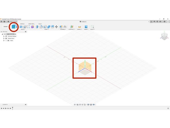
Click the "Create Sketch" button (red circle), then, select the XY or "top" plane (red rectangle)
-
Maneuver the view to a plan view, this can be accomplished by selecting "Top" on the view cube
-
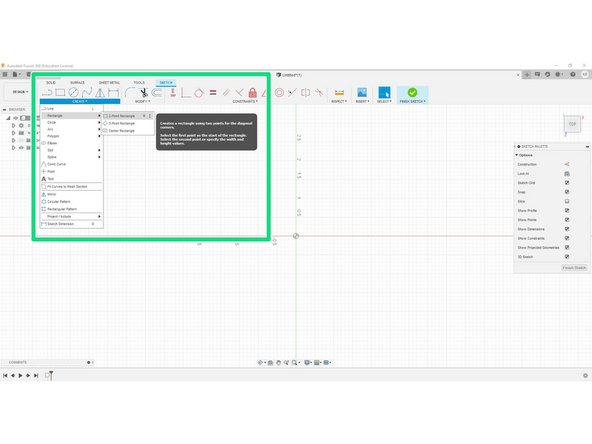
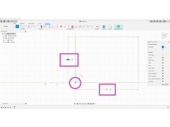
In the "sketch" tab, click the drop down menu named "create," and click "rectangle" and then "2-point rectangle"
-
First click in the origin (pink circle), then type in the dimensions (pink rectangles) you found on the drawing (3.94 x 5.42) and hit enter
-
Type in one dimension number, then TABing will take you to he other number
-
-
-
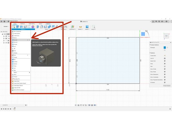
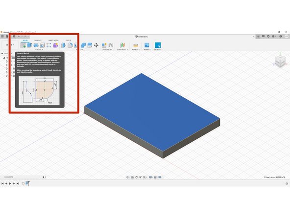
Now that we have our rectangle in 2D, we will simply extrude it out
-
Begin by going to the "solid" tab, and dropping down the "create" button, and select extrude from the option
-
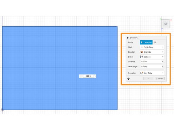
This will then prompt an "extrusion command center" as shown by the orange square, there isn't much to do here except type in our thickness and enter
-
For any questions on what any of the options mean, ask any IFL staffers or slack Kenny Davis Jr
-
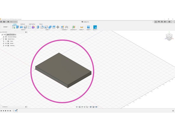
When finished, it should look like the pink circle
-
-
-
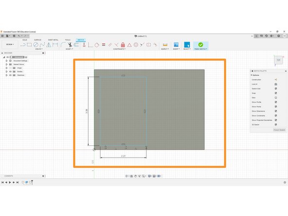
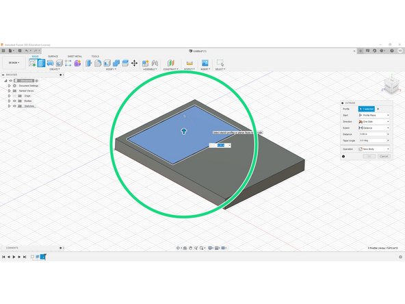
We will begin by creating a square on the top, and extrude cutting through
-
Begin by selecting the top surface, and then selecting "create new sketch (red rectangle)
-
Change the view to the "top" view, an draw a rectangle (look at step 4, the green sub-bullet) with the dimensions from the drawing (2.27 x 3.38)
-
Location can be approximate
-
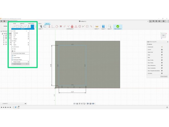
Next, we are going to define where it is with reference to the outer body
-
Select the dimension tool (green square) by going to "create" and the clicking "dimension all the way at the bottom
-
Continue on to part 2
-
-
-
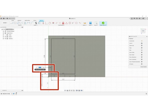
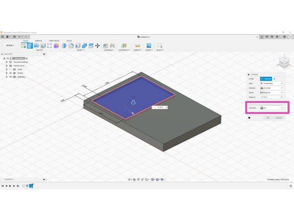
Dimension from the outer edge to the rectangle both .28" (red squares)
-
Then, go to the "solids" and select "extrude"
-
For the body we are extruding, be sure sure to select the inside of the rectangle we drew in step 6
-
Now input .12 in but make sure that the operation is set to "cut" (pink square), and hit enter to see the new cut feature
-
-
-
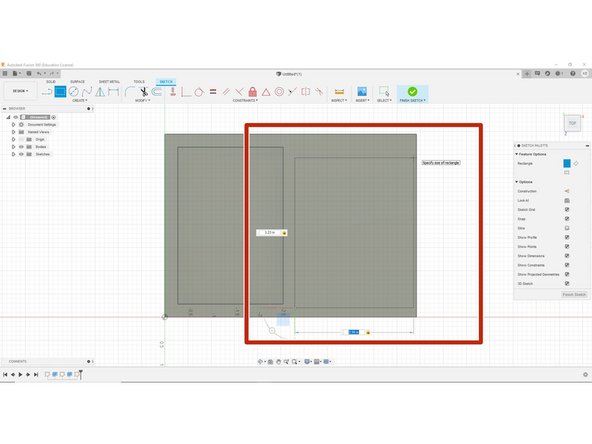
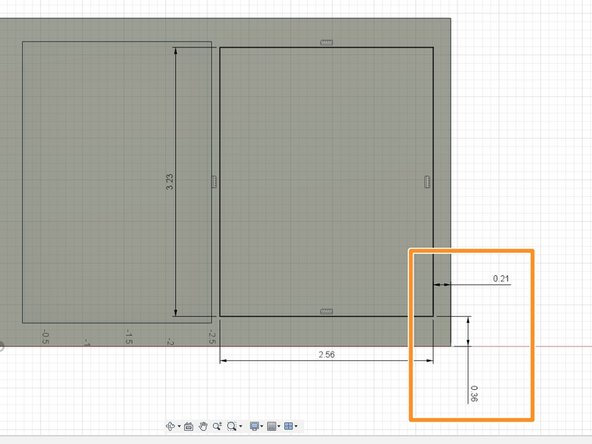
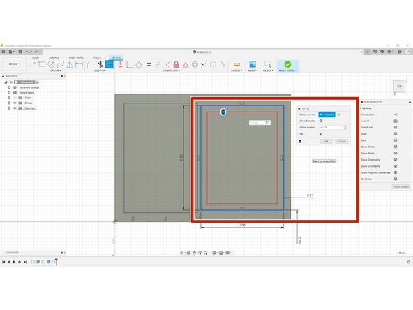
Let's first begin by selecting our top surface again and drawing 1 rectangle (2.56 x 3.23)(red rectangle)
-
Now let's dimension off our rectangle, select the dimension tool, and offset .36X and -.21Y (orange rectangle)
-
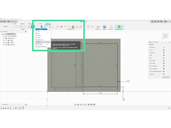
Finally, in order to create a uniform wall thickness, let us select our offset tool by going "Modify" in the "Sketch" tab, from here drop down the menu and select "Offset"
-
-
-
Now with the offset tool selected, we can select the rectangle we just drew, and type our thickness of -.2"
-
The reason the value is negative is simply because the offset would go on the outside if it were positive, if you are unsure what I mean, type in .2" and see what happens
-
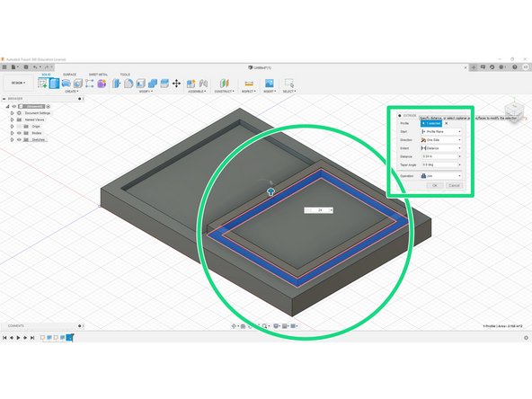
With the outline of the arduino wall, we can now extrude, go ahead and select extrude, then extrude out the wall region we just offset by .24"
-
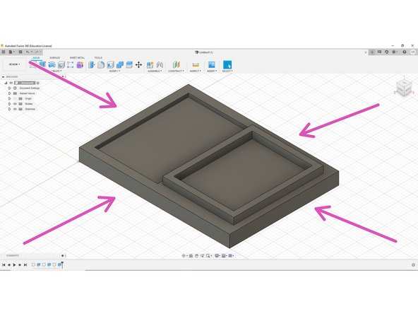
When finished, the part should now look like the last figure
-
-
-
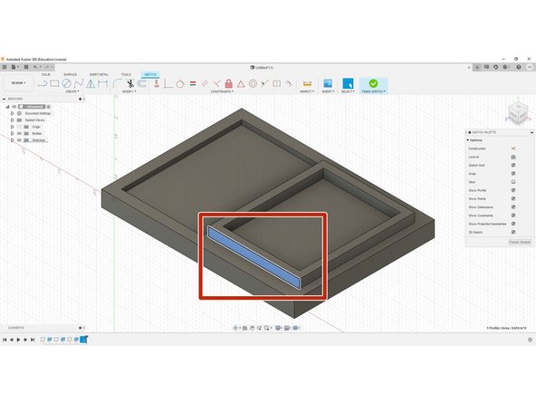
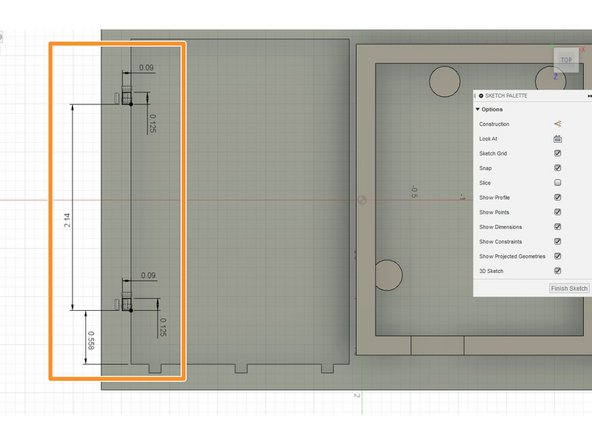
Begin by creating a sketch on the right facing wall we just created, and go into plan view
-
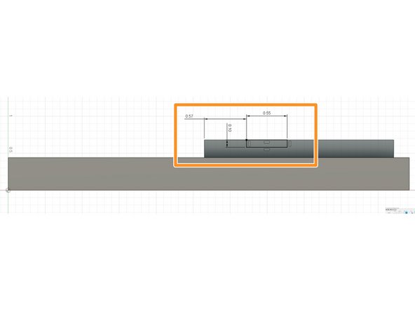
Next create 2 point rectangle, and make sure to select the top line first as shown by the arrow, and input the dimensions .55x and .1z
-
Selecting the top line will create a relationship where the point of the rectangle is "hooked" to the top, and this is exactly what we need
-
Dimension .57" from the outside of the wall
-
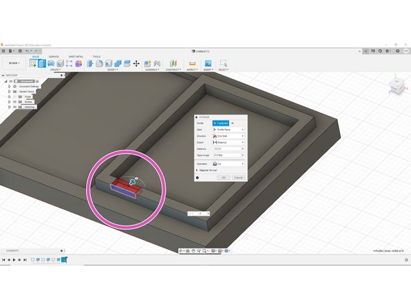
Now simply select extrude, and cut away -.2" (the thickness of the wall)
-
Remember cutting away requires a negative distance
-
-
-
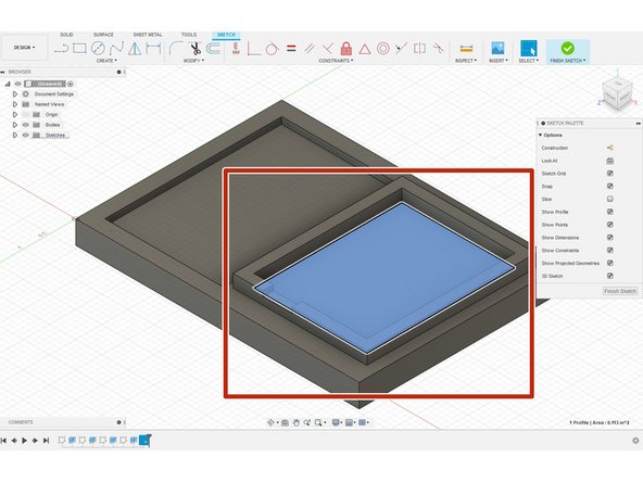
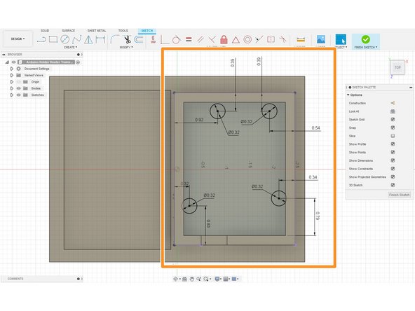
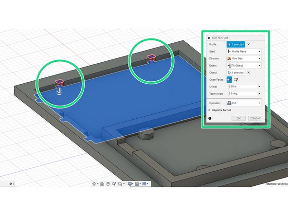
Begin by selecting the surface where the Arduino goes, then start a new drawing.
-
Draw the sketch given in the second photo. All of the distances and lengths are given.
-
Be sure not to leave any blue lines, which means the sketch has undefined properties.
-
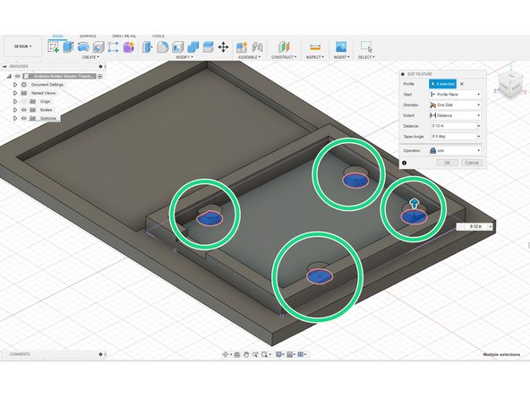
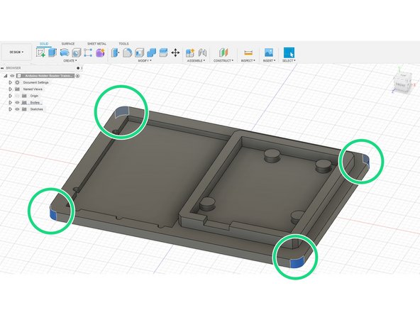
When finished, simply select the four circles and "extrude" shown by the green circles. Make is ".12" tall.
-
-
-
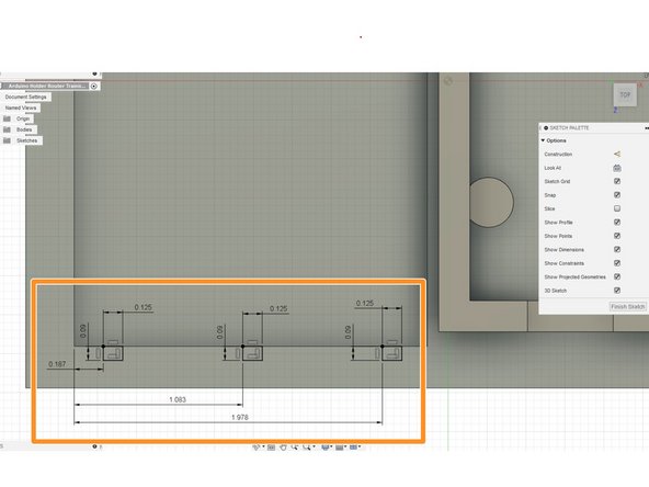
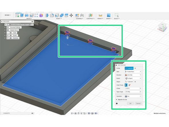
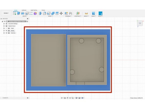
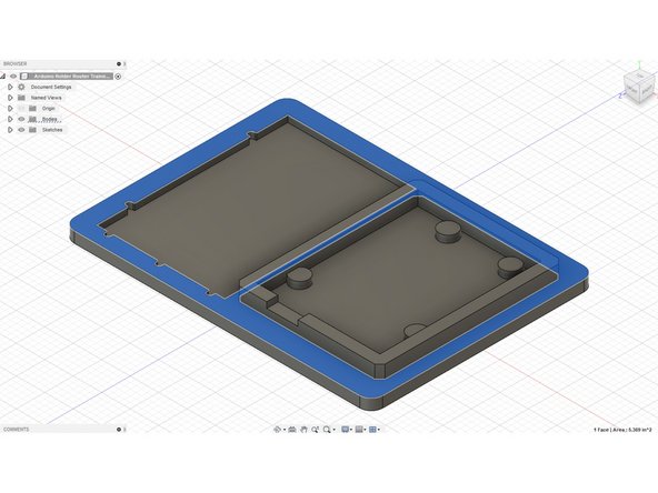
Begin by selecting the surface in blue, as shown by the red rectangle.
-
Create a new sketch, and draw 3 rectangles as shown in the second picture. All dimensions are given.
-
Finally, extrude down to the bottom of the breadboard surface. This will cut down to the surface requested, as shown by the red cut away.
-
-
-
Again chose the middle surface as shown by the red rectangle.
-
Use all the dimensions as given by the second picture.
-
Extrude down to the bottom surface.
-
All of the steps are a repeat of the previous step.
-
-
-
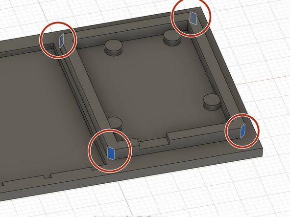
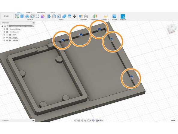
Begin with the chamfers on the Arduino older. Select all the corners in the red circle and select "chamfer."
-
The chamfer should be .09"
-
Next, select the "radius" tool and select the inside corners of all 5 rectangles we drew for the breadboard cutout.
-
The radius should be .0625"
-
Lastly, select all four corners of the part, shown in the green circles.
-
Radius to .2"
-
-
-
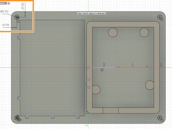
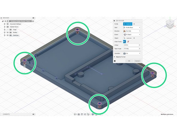
Began by selecting the middle surface again. Create a sketch off here.
-
Draw 4 circles at .15" in diameter, and .2" off the walls, as shown by the orange circles.
-
If more advanced, draw one circle and mirror it over, but this is not necessary.
-
Lastly, extrude all 4 circles "through all."
-
-
-
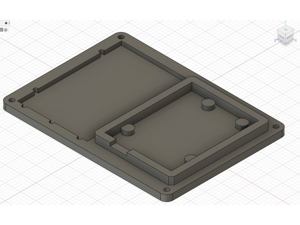
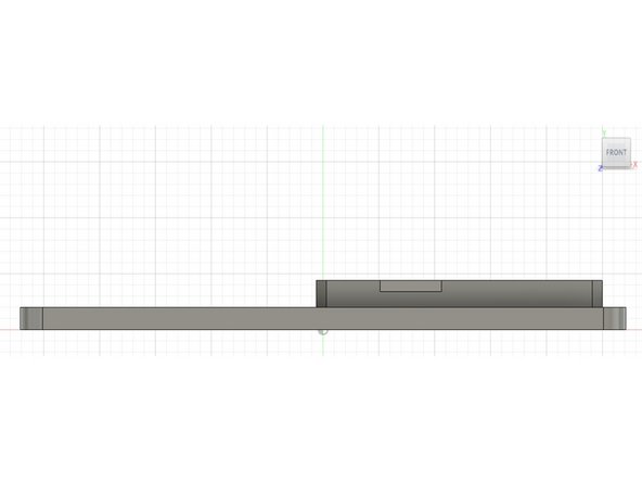
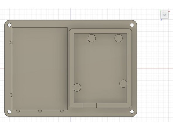
Here are 3 different views of what the finished part should look like.
-