Tools
Parts
No parts specified.
-
-
Creating a rectangle on top will allow us to easily create a facing feature
-
Begin by clicking on the topmost surface, and create a sketch
-
Then, draw a rectangle around the top, and make it 6 x 4.5". Centering is optional (use relationships)
-
The last photo is a finished view.
-
-
-
This is where we will begin our CAM. CAM stands for computer-aided design, and thus a tool integrated right into Fusion 360 that allows us to create G-code.
-
Over in the left toolbar where it says "Design," drop down the menu and select "Manufacture."
-
Next, we need to create a new setup. Click the new setup button as shown by the orange rectangle, or taskbar.
-
For more complicated parts with a top and bottom, multiple setups can be used. But we will only have one for this guide.
-
After selecting the new setup button, it will bring up a menu for setting orientation and stock size.
-
-
-
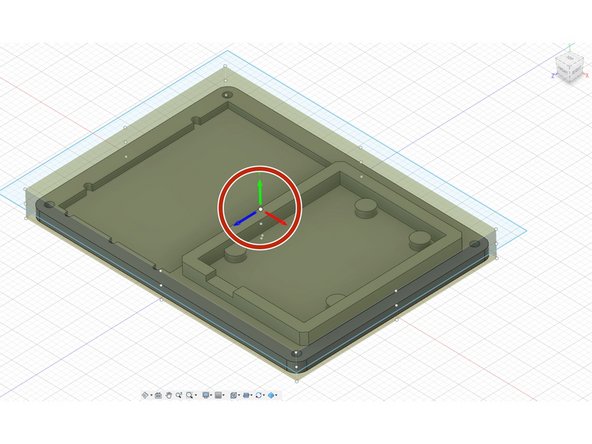
For orientation, we always keep the same model. The positive Z-axis is the spindle. The X and Y-axis are up to the user, but the red rectangle shows how both are orientated.
-
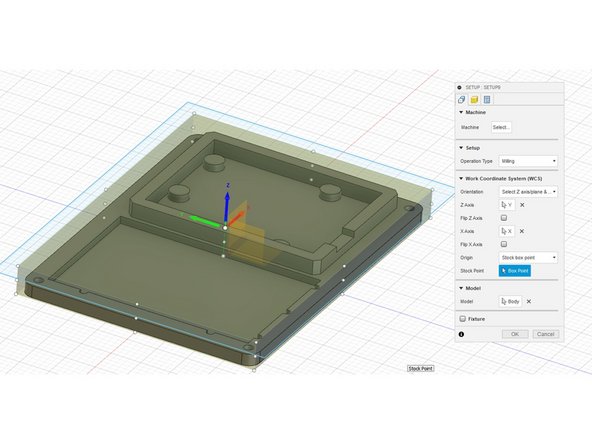
The first option for most operations is the "Stock Point." Always be sure to select the top middle point.
-
* NOTE - sometimes while doing the setup, this can jump on you. If it ever does just be sure to select "Stock Point," and choose the top middle again.
-
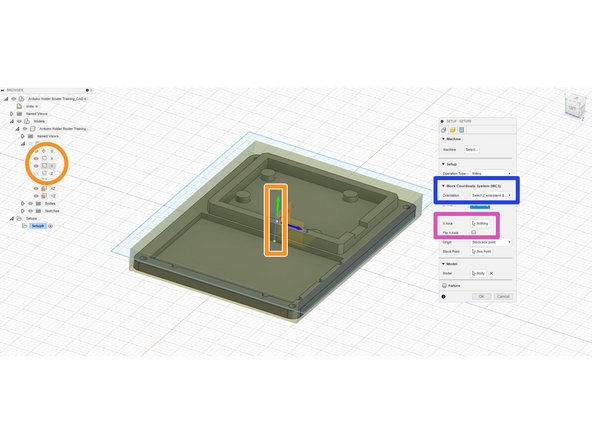
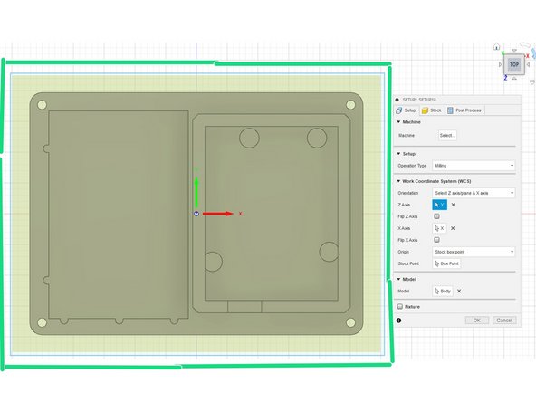
In the menu, navigate to the "Work Coordinate System" and drop down the menu for "Orientation." In this dropdown, select the "Select Z axis/plane & X-axis" option.
-
Now on the menu, the selection for the Z-axis should be highlighted. Navigate through the part origins, and select the axis that is "coming out of the part." (In the picture shown, it was the Y-axis)
-
For the X-axis, select the best axis option for the particular part. In our case, it is how we orient the part.
-
Lastly, just double-check the "Stock Point" and validate it is in the top middle.
-
-
-
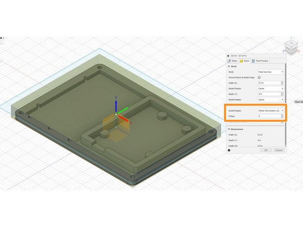
For setting the stock size, follow all the steps here. But the actual length, width, and thickness can be varied to particular needs and what is available.
-
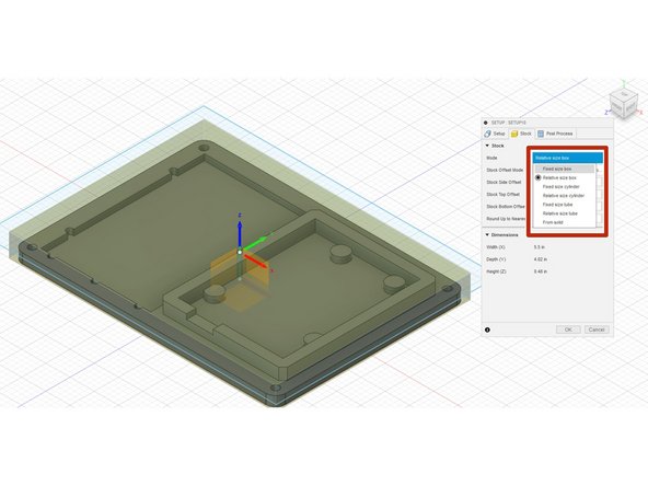
On the pop-up bar select "stock," and navigate down to "mode." Change this to "Fixed Box Size."
-
Type in the X and Y dimensions available, or copy 6 x 4.5" For the Z-axis, drop down the menu by "Model Position" and select "Offset from Bottom (-Z)." Then make sure this offset is 0". My thickness is .75"
-
Lastly just change te view around the model, making sure the stock completely covers the part. Shown in the green is the top, which was my check.
-
-
-
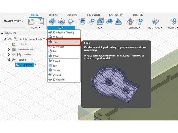
The Face operation will cut-away material to bring the top material down closer to the part.
-
Select the "Face" operation by dropping down the menu for "2D," and electing "Face."
-
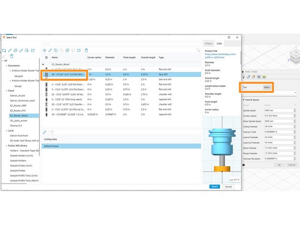
By tool, click "select." Navigate to the EZ_Router_Wood library and select the face tool "30 - 1.5 Diameter."
-
The facing tool usually has a bigger base at the bottom as shown in the photo.
-
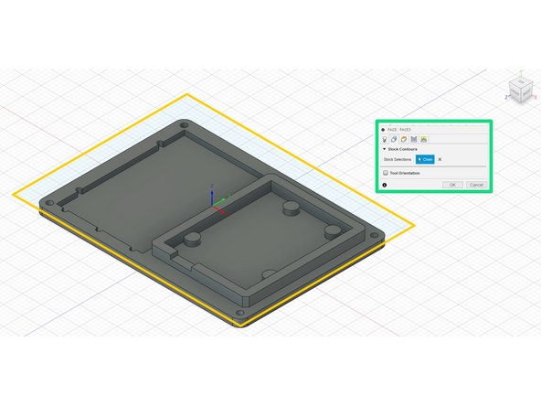
Going in line with the next option, geometry. Simply select the rectangle we drew in step 1, and the words will change to "chain."
-
-
-
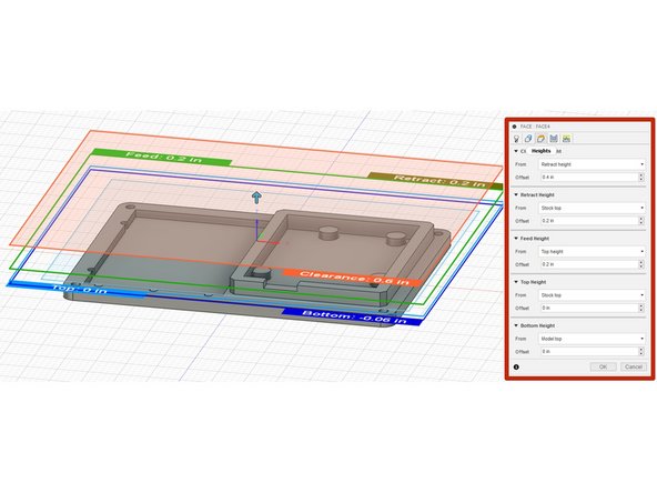
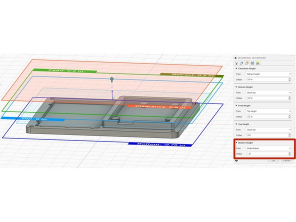
Next in the "Heights" tab, there is nothing we need to change but verify. If all the values are shown as in the red rectangle, you are golden.
-
Bottom Height - The lowest height the operation will mill. Top Height - usually just the top of the model. Feed Height - the height at which the spindles starts to rotate, and the height linking moves are made. Clearance Height - should always be above all features on a model. Retract Height - the height at which the machine will retract the tool.
-
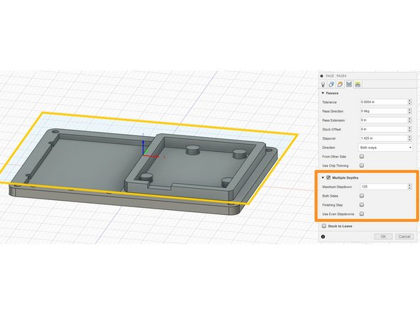
On the passes tab, select the "Multiple Depths" option, and set the "Maximum Stepdown" to .125" and click "OK" at the bottom.
-
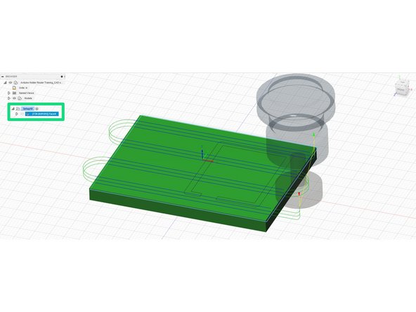
After the simulation should be shown after clicking on the face operation in the structure tree to the left.
-
-
-
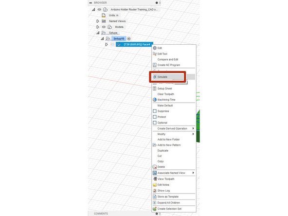
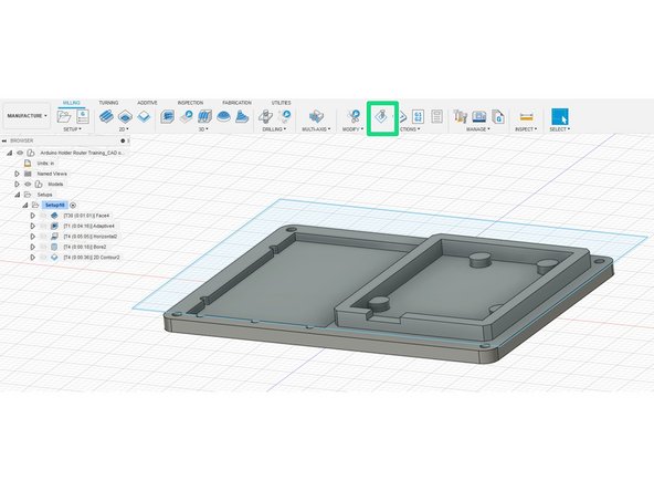
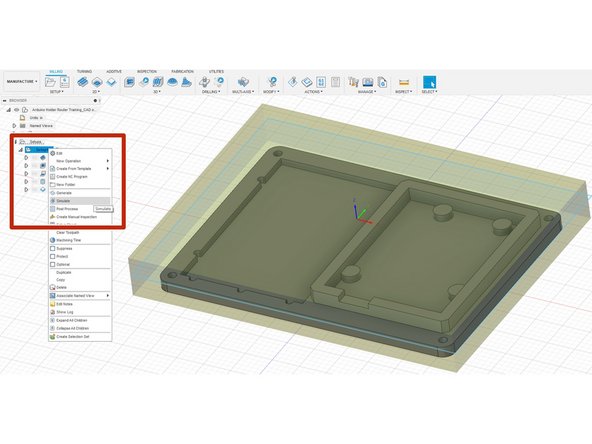
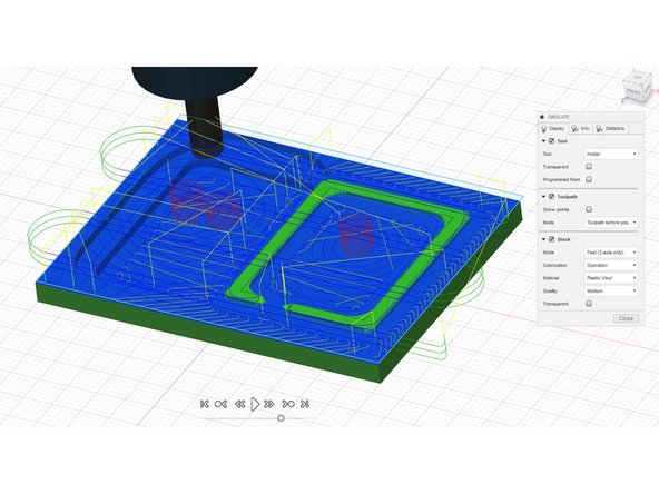
Right-click the operation you want to simulate and select "Simulate."
-
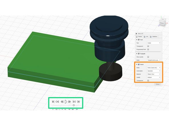
When the menu pops-up, be sure to select the "stock" option. This will allow everything to be seen more clearly.
-
On the bottom, a simulation menu will be available. By selecting the play, you can see the whole simulation. There is also a fast-forward, fast-reverse, and skip to end buttons.
-
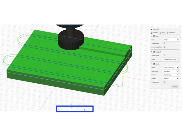
The sliding bar is the speed. It can be adjusted to however fast or slow you would like.
-
When finished click "Close" on the bottom of the pop-up box.
-
-
-
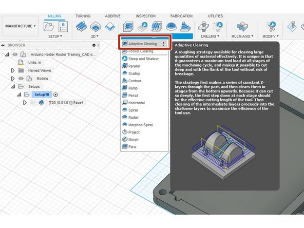
3D Adaptive clearing will cut away a lot of material at once, but will not me the finishing touch.
-
Go to the 3D drop-down menu, and select "Adaptive clearing."
-
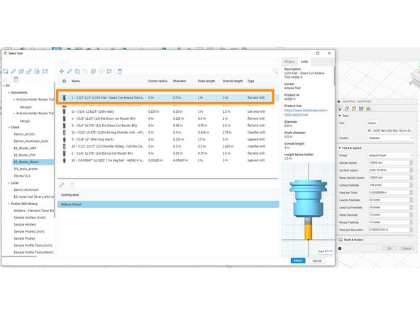
For the tool, we are going to use a 1/2" end mill. At the machine, we will use the anama tool but simply select the #1 1/2 diameter end mill.
-
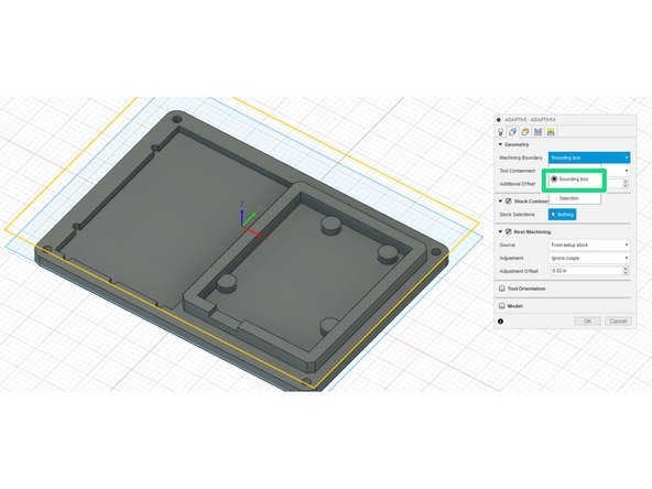
In the geometries tab under "Machining Boundry" select "Bounding Box." This will bound all operations to a specific area.
-
-
-
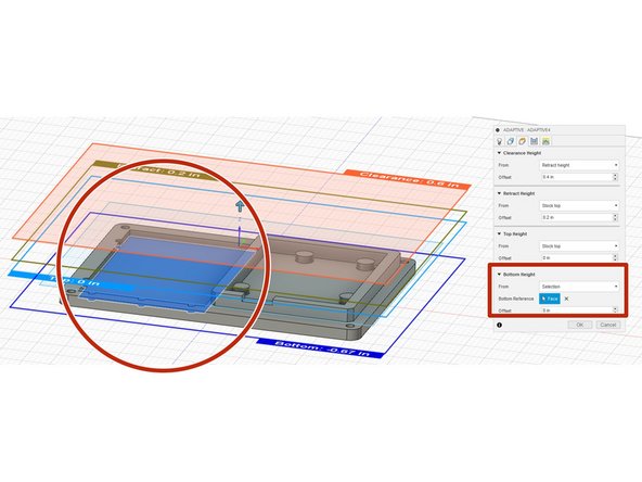
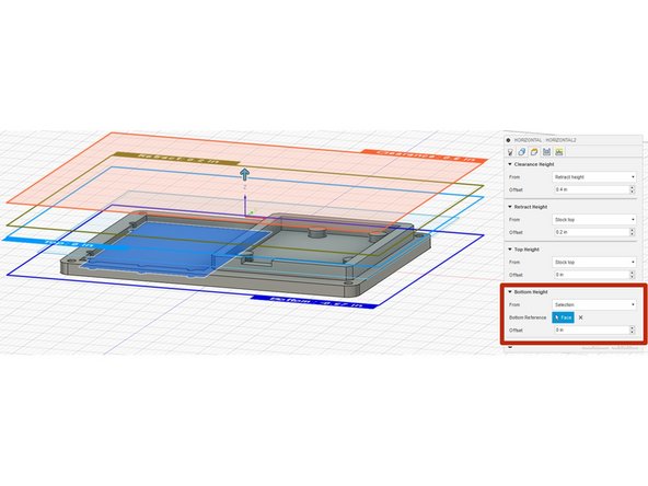
Next, go to the heights tab. Scroll down to the "Bottom Height" row and drop down the menu, selecting "Selection." Now select the lowest contour pocket (the breadboard cutout).
-
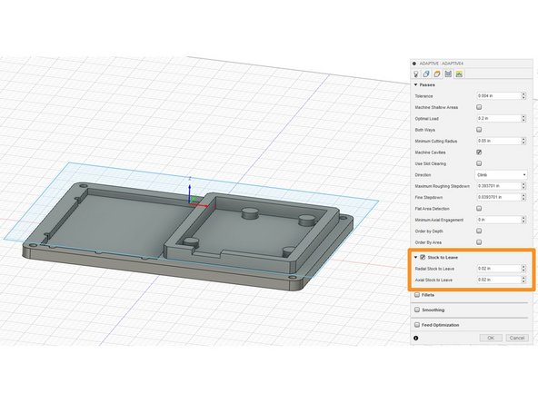
In the passes tab, make sure "Stock to Leave" is checked. Set both values to .02".
-
Stock to leave is essential for a fast, smooth finish. With the adaptive clearing, we are just getting rid of tons of material at once. Later on, we will come back and "polish" it.
-
When finished, select "OK" and simulate to check for any errors.
-
-
-
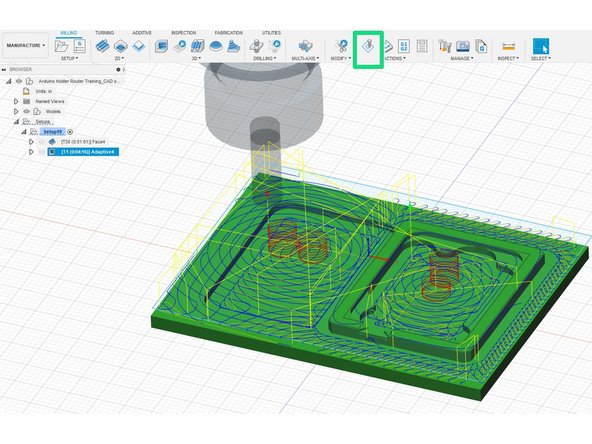
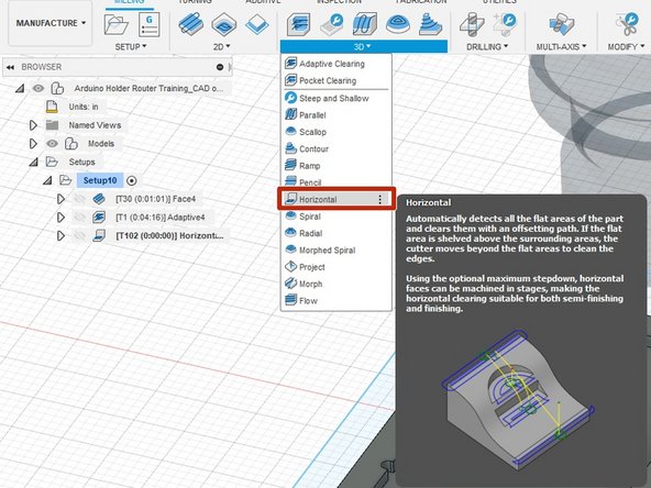
Select the "Horizontal" operation in the "3D" column.
-
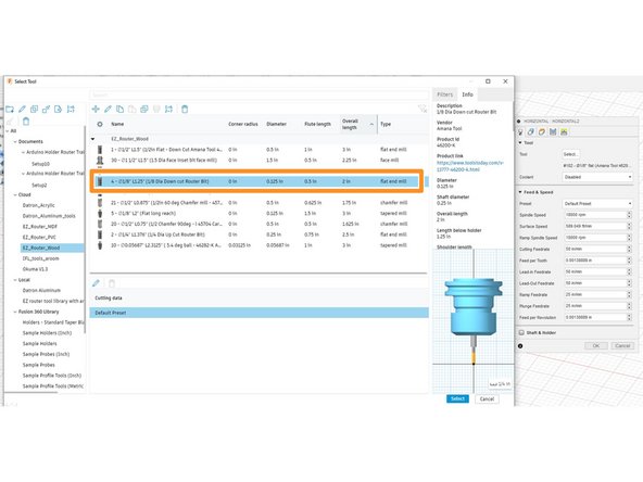
For this operation, we will be using the 1/8" anama tool. Select the # 4 1/8" flat end mill tool.
-
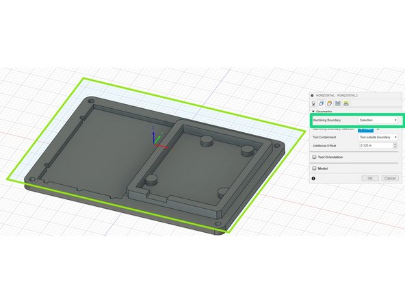
For geometries, we will copy the same operation we completed for adaptive clearing. Change "machining boundary" to "Selection" and select the rectangle dawn in step one.
-
-
-
As we did for adaptive clearing, in the "heights tab," in the "bottom height" row, drop down the menu and select "Selection." Then click the lowest pocket (the breadboard pocket).
-
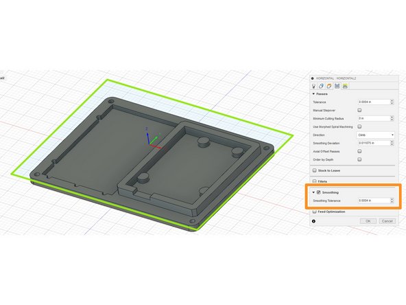
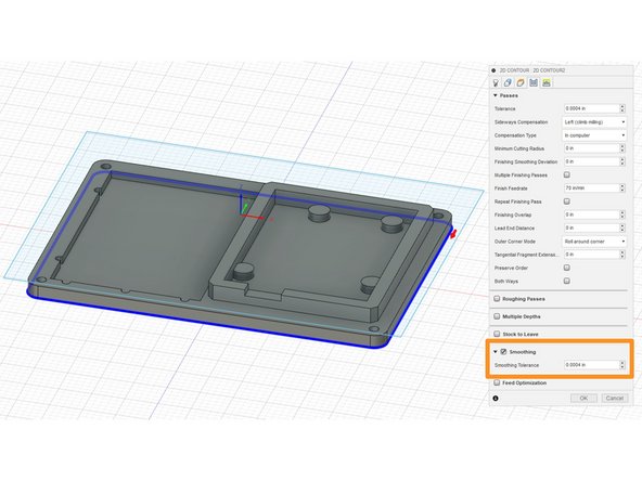
Now go to the passes tab, and click "smoothing." The value should be preset, don't change it.
-
As stated earlier, now we are going to smooth all of the surfaces. This is different from adaptive because we are not taking a lot of material out, so we can use a smaller mill with less strength.
-
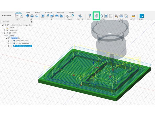
When finished click "OK" and simulate the operation.
-
NOTE - To simulate all the operations, just right-click the setup, and select "simulate."
-
-
-
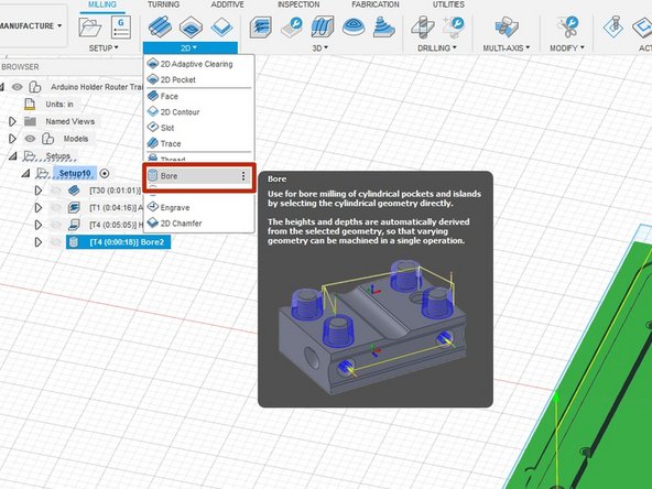
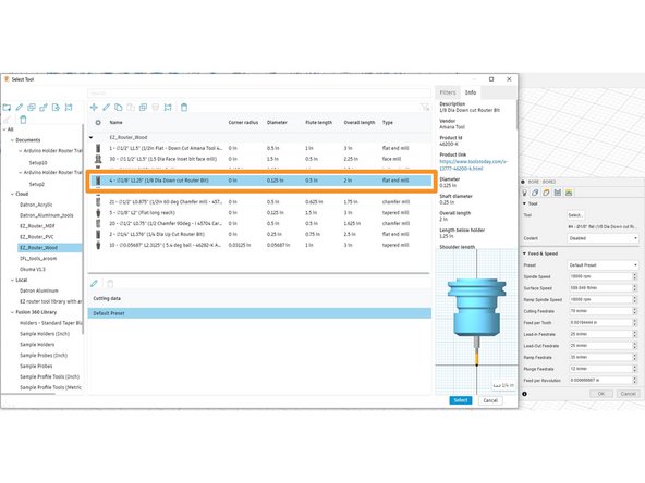
Select the "Bore" operation under "2D."
-
We will be using the same tool used in the previous operation. the #4 1/8" diameter end mill, in the EZ_Router_Wood folder.
-
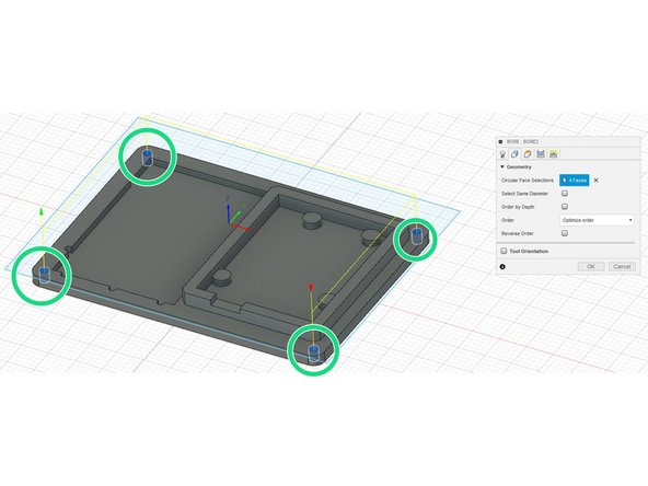
Next in the "Geometry" tab, simply just select the 4 holes on the outsides of the part. We are going to bore with a helix down these holes.
-
-
-
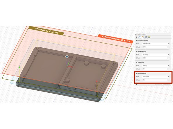
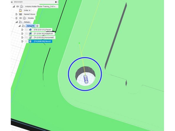
Nothing else needs to change, but verify the "bottom height" in the "Heights" tab is set to "Hole Bottom."
-
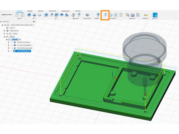
Run the simulation to verify no errors. Remember it would be best to run the full simulation.
-
If zooming into a hole, the helix is clearly visible.
-
The helix is because the end mill is made for milling, not drilling. Therefore by creating a helix, it will "mill" down, and do what the bit is intended for.
-
-
-
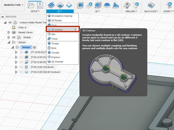
Select the "2D contour" operation in the "2D" tab.
-
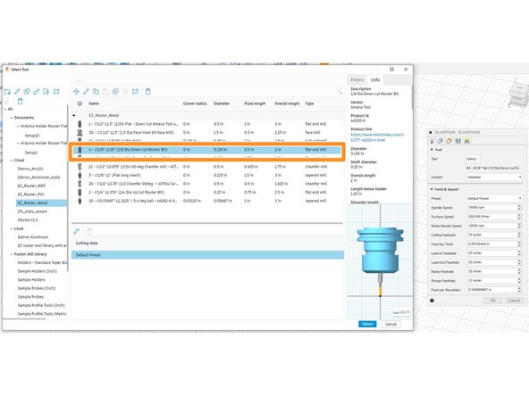
We will be using the same tool used in the previous operation. the #4 1/8" diameter end mill, in the EZ_Router_Wood folder.
-
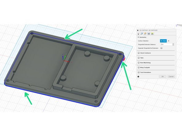
In the geometries tab, select the bottom-most outer contour. (The blue outline, by the green arrows).
-
Remeber we are choosing th bottom-most countour because this operation will cut the part out.
-
-
-
In the "Heights" tab, on the "Bottom Height" row, set the "from" to "model bottom," and offset -.01".
-
We will barely cut into the table, just skimming it to make sure that part is completely cut out.
-
Next in the passes tab, turn on "smoothing." Leave the preset value alone.
-
You can turn on multiple passes if you feel it needs it, but the cut is so small it almost unnecessary.
-
Lastly, simulate to check for errors.
-
-
-
ALWAYS DO A FULL SIMULATION AND ADDRESS ALL ERRORS BEFORE CUTTING AT THE MACHINE
-
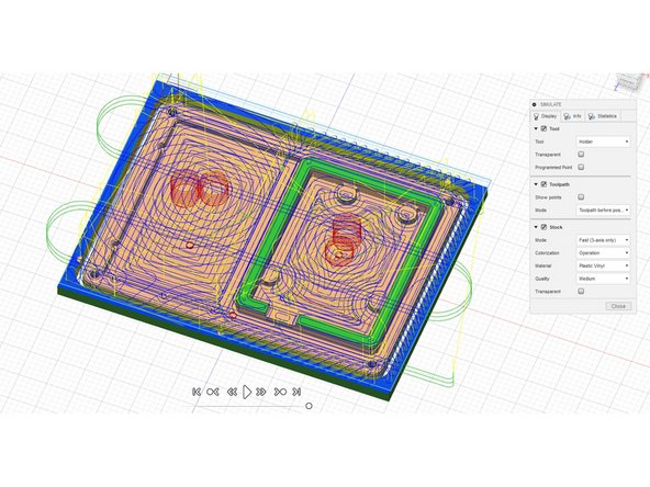
As previously stated, right-click on the setup and simulate.
-
Play the whole simulation through, looking for errors.
-
When finished the part should be cut out.
-
-
-
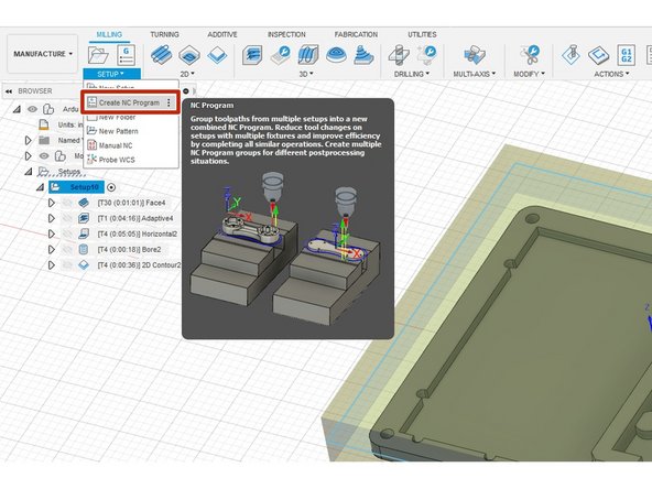
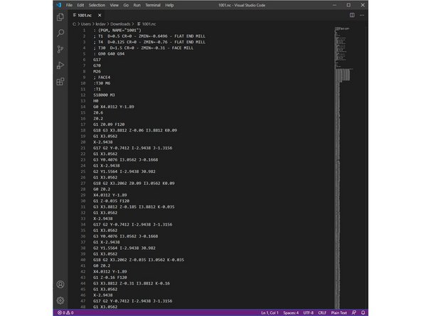
Click the "Create NC" program. This will generate the G-code the EZ-router CNC machine.
-
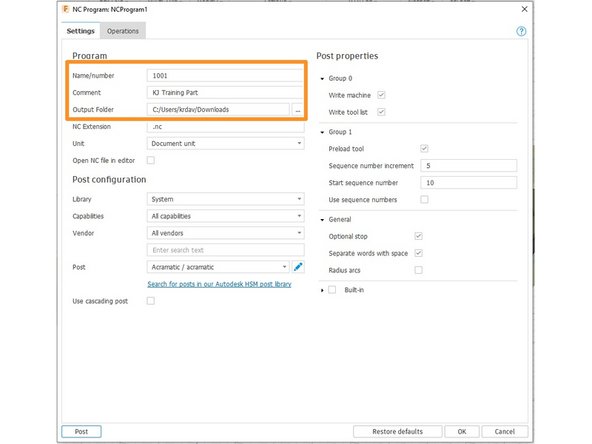
Create a unique 4-digit number for the "Name/number." Then put a comment for some clarity as to what the program is. Lastly, set the "Output Folder" to where you want the NC program to output, most likely a removable drive.
-
When finished click "OK" and the G-code program has now been exported. The G-code commands the EZ-Router to follow a set of instructions.
-