-
-
Grab a lab manager and give them a lab safety tour, just like you would a student!
-
Feel free to ask the staffer you grab any questions about lab safety and training.
-
-
-
Make sure to complete the LM Daily Responsibilities upon entering/using/leaving the space.
-
-
-
-
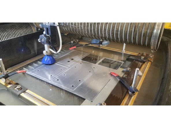
You will be getting trained on the Protomax Water Jet.
-
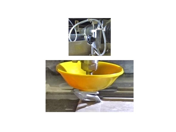
The location of the power switch/emergency stop button is shown in the second picture
-
-
-
The cost of using the waterjet is $25/hr of cutting + $1 per lb of garnet used.
-
Once you load your file inth the make software, the machine will show you how much time and garnet it will use . More on this later.
-
When determining the cost of a job, round up to the nearest half hour and pound of garnet.
-
-
-
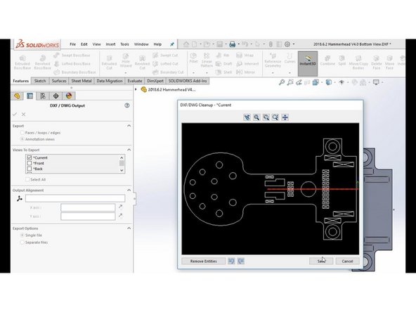
The waterjet uses the DXF (.dxf) file format
-
When exporting a CAD file you can choose DXF from the file type options
-
-
-
Transfer the DXF file to the laptop connected to the waterjet
-
You can make a folder in documents/downloads with your name for convenience or work directly off of a flashdrive
-
-
-
This software can be found in the computers around the lab. However, you can download it on your computer if you wish.
-
-
-
-
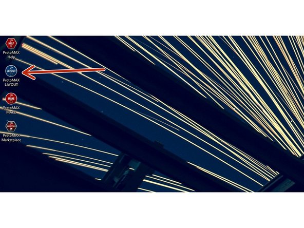
The first step is to prepare the DXF file in Protomax LAYOUT
-
Open the program indicated in the picture. It should be on the Desktop.
-
-
-
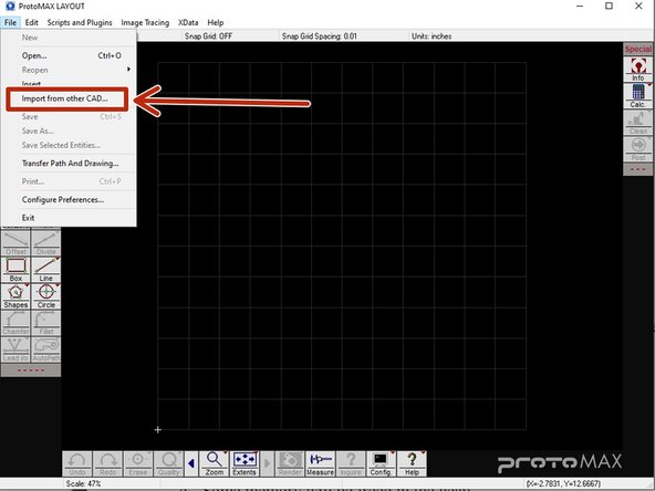
Once the software is open, go to the FILE tab and click the "Import from other CAD" option, as indicated in the picture
-
Select the DXF file you want to import
-
-
-
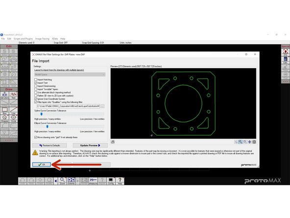
When you select your file, this window will appear
-
For most jobs these settings will not need to be adjusted
-
If you have custom settings for your part regarding precision, please ask for help before doing anything.
-
-
-
When the DXF is imported it is often placed in a random position outside of the cutting area (the 12x12 grid on screen)
-
Use the Move tool to place it on the grid in the desired position
-
Select the Move tool by either clicking on it or pressing CTRL+M on the keyboard
-
Click the part you want to move and then click on the location you want to move it to
-
-
-
The imported file will often be the wrong size. This can be corrected with the Size tool.
-
Click on the part you want to resize then click the Size tool
-
This will open a new window where you can alter the size of the part either by scaling it or by directly altering the dimensions (in inches)
-
You can check the size of the part with the Measure tool
-
-
-
You can adjust the quality of the cut by going to "Edit"->"Set Quality"->"All"
-
If you only want to alter certain lines, select the ones you want to change then go to "Edit"-->"Set Quality"-->"Selected"
-
The higher the quality number, the slower the cut
-
-
-
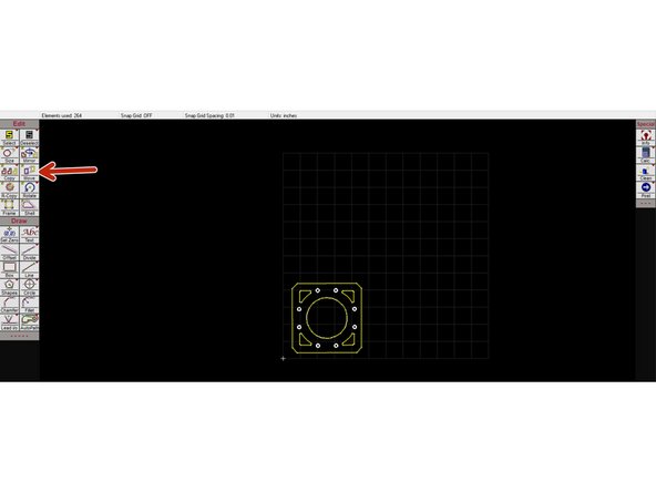
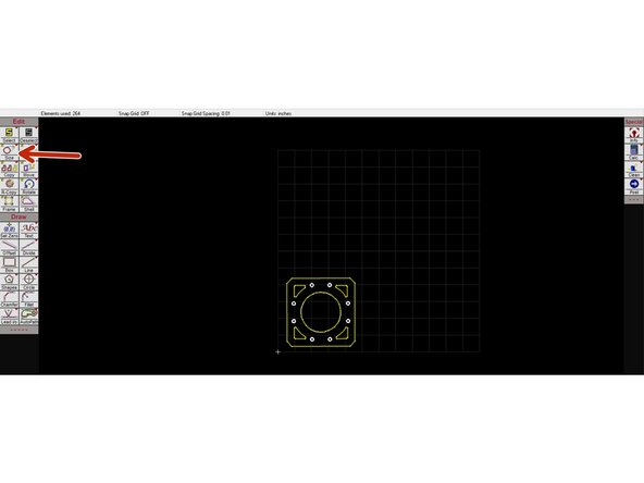
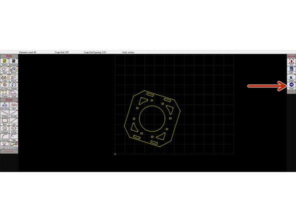
After you finish adjusting the part's position and properties the part needs to be cleaned
-
This removes any potential gaps in the file and ensures that cuts will be unbroken lines
-
Following the steps in the pictures
-
Click the "Clean" button on the right hand side of the screen to open the cleaning window
-
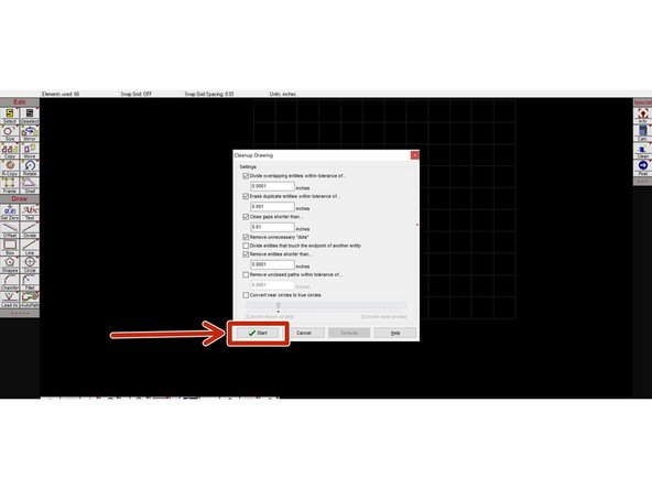
Click the "Start" button to start the cleaning process
-
The next window will list the adjustments and fixes that were made. Click "Ok" to close
-
Repeat the cleaning step at least two times, to ensure that the part is clean of openings
-
-
-
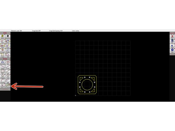
The next step is to add the tool path with the "Autopath" tool. This is the path the waterjet will follow when making its cuts and when moving between cutting spots
-
The green line is the non-cutting path
-
Click the "Autopath" button to generate the path
-
-
-
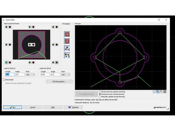
Sometimes you will need to make adjustments to the autopath
-
Right click "Autopath" and click "Autopath (Advanced & Configure)" from the options that appear
-
The tool in the upper left allows you to adjust the location of the start and end points
-
The green buttons set the start point to the side of the part that you click and the red buttons do the same for the end point
-
Lead In and Lead Out are the distances that the nozzle will travel from the part to the start and end points, respectively
-
You shouldn't need to change any other settings
-
-
-
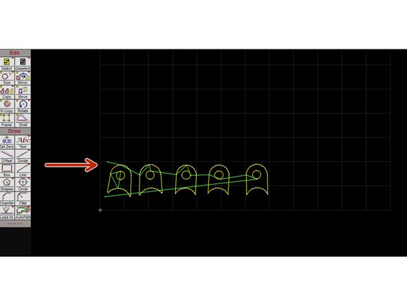
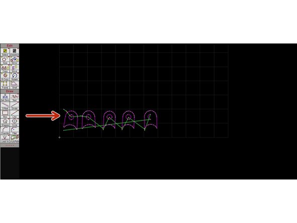
After the Autopath is done you have to check if the path is unbroken
-
The first picture shows a broken path resulting from gaps in the DXF
-
If this happens, remove the autopath by right clicking on the "Autopath" button and selecting "button name". Run the cleaning process again before attempting to use autopath again
-
The second picture shows an unbroken path
-
-
-
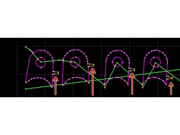
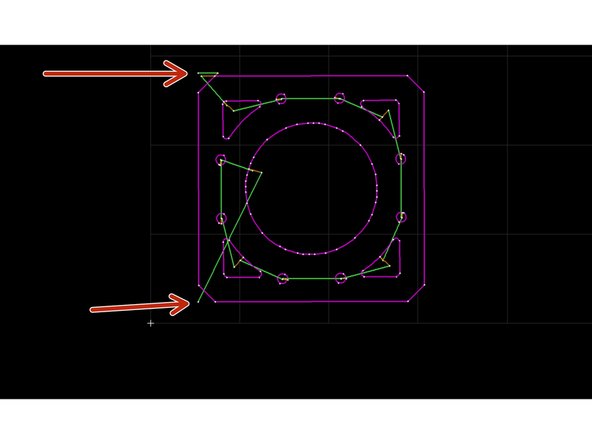
If the parts being cut are small enough to fall between the slats of the waterjet you will need to add tabs to keep them in place
-
Only add tabs after the part has been cleaned and autopath has been completed
-
Hold CTRL-T to enable the tabs option
-
You can then add tabs to the cutting path (the purple line) in your desired orientation, as shown in the picture
-
-
-
Once everything is done, select the "Post" option on the right hand of the screen
-
-
-
You will be taken to another screen where it will ask you to choose the start position for the path
-
Select one of the two path endpoints that are off of the part
-
The options for the example part are indicated in the picture
-
-
-
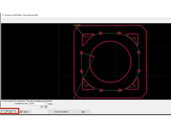
If you have any settings that you want for the toolset, you can change them here
-
In most cases the settings will be left as is
-
Select save
-
Simply clicking the "Save" button will save the MAKE file to the same folder as the original LAYOUT file. If you want to save it in a different location you will need to right click on the "Save" button and select "Button name". Then select your desired file location and click save
-
-
-
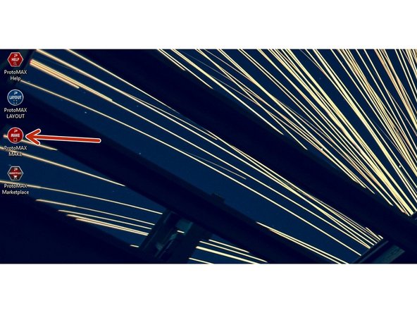
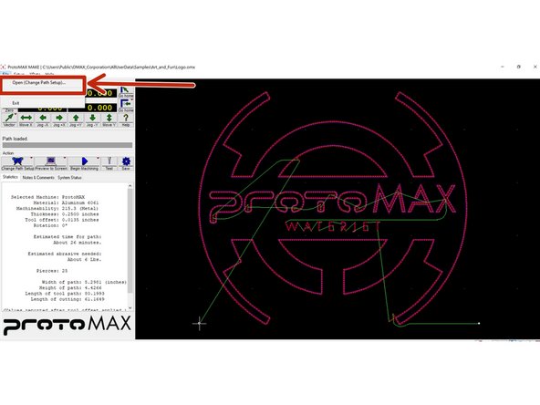
The next step is to send the file to the waterjet using Protomax MAKE
-
Open the program indicated in the picture. It should be on the Desktop.
-
-
-
Go to FILE and select "Open (change path file)"
-
Choose the LAYOUT file from your local directory/file
-
-
-
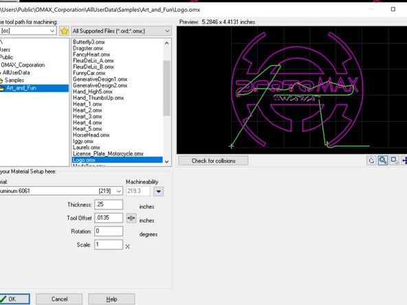
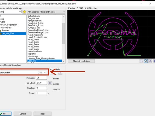
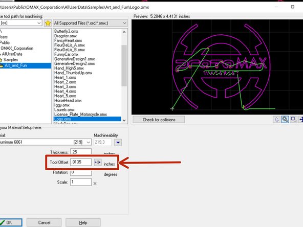
Click on the drop down menu and select the material you will be cutting (Picture 1)
-
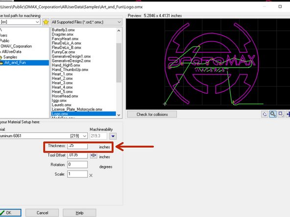
Input the thickness of the material you are cutting in INCHES (Picture 2)
-
The offset (picture 3) is how precise the cut of the water jet will be. This will usually be left alone and should match the offset of the imported LAYOUT file
-
Once all the information is correctly entered, click "Ok"
-
-
-
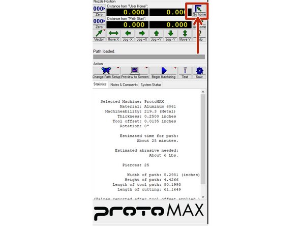
After importing the part reset the home position of the nozzle by clicking the button indicated in the picture
-
-
-
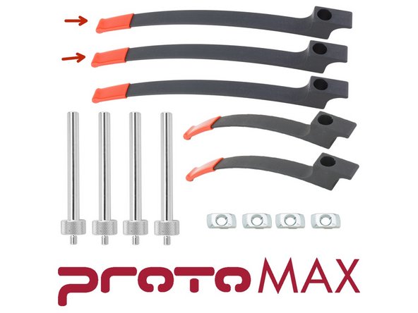
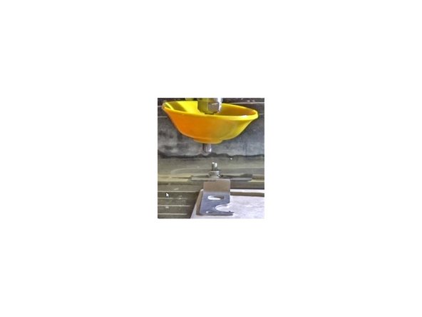
The clamps used to secure the stock material to the cutting bed can be found in the tray hanging from the left side of the machine
-
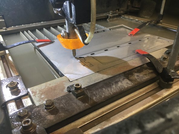
Insert the spokes into the grooves along the sides of the cutting area and rotate them until they are locked in place. Add clamps of appropriate length, as shown in picture 2
-
Make sure the clamps are not in the way of the cutting path
-
-
-
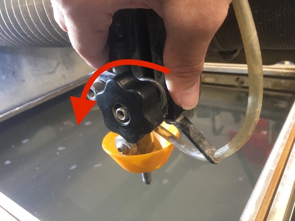
After the part is secured, nozzle height Needs to be calibrated manually
-
With one hand on the large black block at the base of the nozzle, loosen the nozzle height adjustment knob to allow it to be moved up and down
-
Always keep one hand on the base of the nozzle to keep it from dropping down and smashing into the cutting material
-
-
-
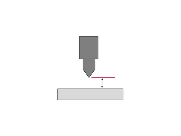
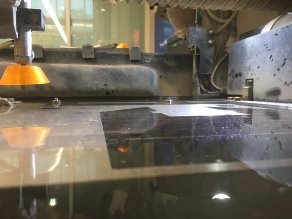
The nozzle stand-off for the ProtoMAX must be set to .075 in. using the provided feeler gauge.
-
Set the feeler gauge down on the material just below the nozzle tip.
-
Carefully lower the nozzle until it is touching the feeler gauge
-
Tighten the nozzle height adjustment knob to lock the nozzle position in place at the .075 in. stand-off height.
-
Remove the feeler gauge. The stand-off height is now correctly set.
-
-
-
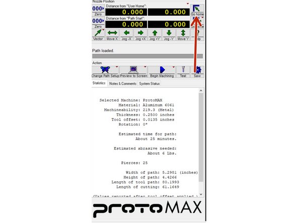
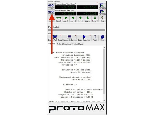
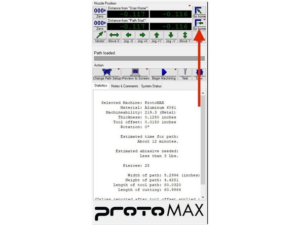
First home the nozzle using the button shown in the first picture
-
Use the arrow keys on the keyboard or the movement buttons on the screen to move the nozzle to where you want the start point of the tool path to be located
-
Click the "Zero" button on the lower row of coordinates, as shown in the second picture
-
The nozzle can now be returned to this position by clicking the lower "Go Home" button (picture 3)
-
-
-
Use the hose in the sink next to the waterjet to raise the water level in the machine until it is just above the stock material
-
Make sure that the water drainage tube on the right side of the tank is lifted up so that the water does not get too low mid-cut
-
-
-
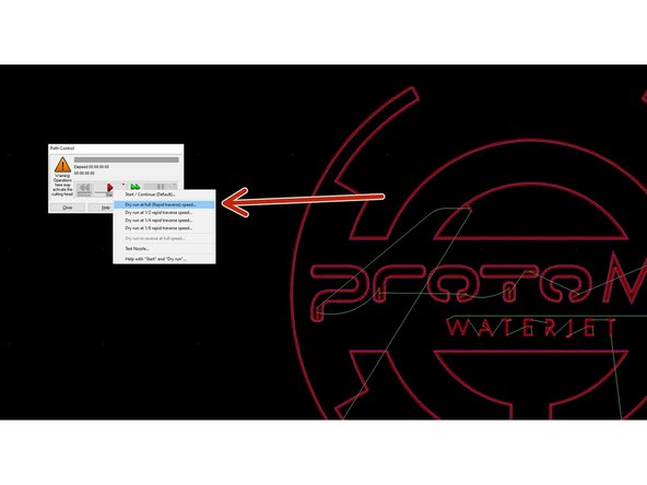
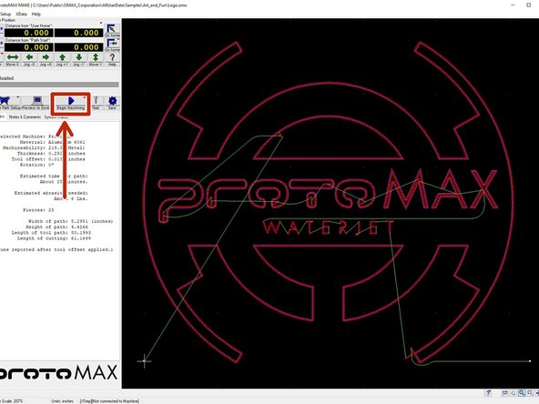
Select the "Begin Machining"
-
Right click on the button shown in picture 2 and select "Dry Run at Full", as shown in picture 3
-
Watch the machine as it traces the path that it will follow
-
Make sure that the nozzle will not hit any clamps and stays on the material
-
If there is an issue with the path, set a new home by following the directions in step 25
-
-
-
Once you are satisfied with the path the tool will follow, make sure that the splash guard is concave side down and close the lid of the machine by disengaging the latch and lowering the lid without letting it fall
-
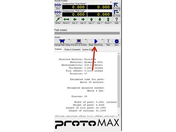
Send the nozzle back to the new home position by selecting the lower "Go Home" button, shown in picture 1
-
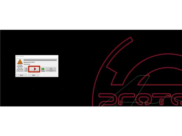
Select "Begin Machining" (picture 2) then start the machining process, as shown in picture 3
-
-
-
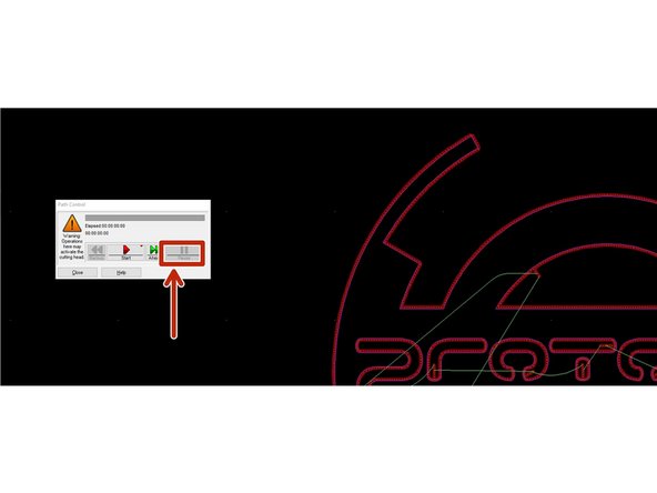
If something goes wrong, while the nozzle is cutting the material hit the "Pause" button and resolve the issue
-
If the problem is non-catastrophic you can click "Resume" once it is resolved
-
-
-
After the cut is done, raise the nozzle so it is out of the way
-
Take out the material and the part
-
If the part had tabs you can remove the material and extract the part using other tools in the shop
-
-
-
Remove the clamps and clamp posts and return them to the tray hanging from the left side of the machine
-
Use the water hose to clean the machine bed and remove any garnet that settled on top
-
Reduce the water level of the machine to just below the top of the cutting bed slats by lowering the water tube on the right side of the machine
-
-
-
The nozzle should be cleaned before turning the machine off for the day
-
There is a separate Dozuki that details this process
-
-
-
-
For your next shift, you will be processing your own .dxf file on the water jet.
-
-
-
All maintenance Dozukis for the waterjet can be found in the link below.
-
-